
New type pressurized water tank

A water tank, a new type of technology, applied in the field of sanitary ware, can solve the problem of not being able to increase the pressure

Inactive Publication Date: 2003-04-30
陈国忠
View PDF0 Cites 2 Cited by
  • Summary
  • Abstract
  • Description
  • Claims
  • Application Information

AI Technical Summary

Problems solved by technology

[0002] The same type of water tank currently used cannot freely adjust the flushing time of the sleeve according to the actual use situation, and cannot increase the pressure

Method used

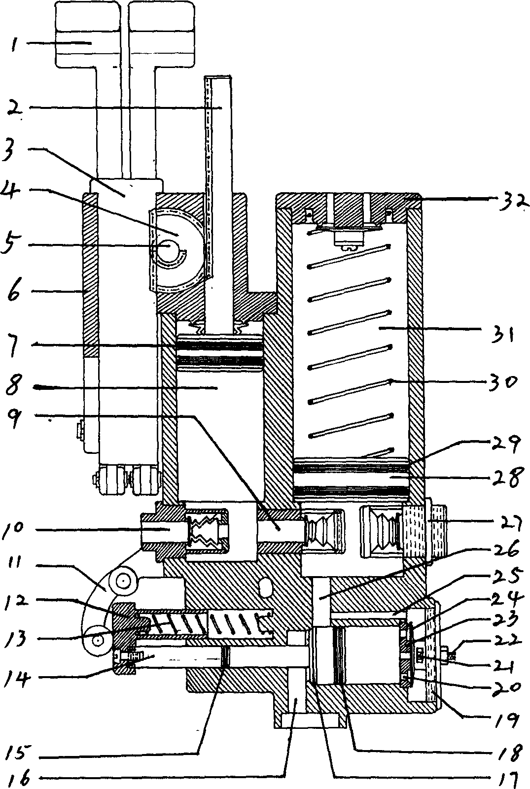

Image

  • New type pressurized water tank
  • New type pressurized water tank
  • New type pressurized water tank

Examples


Embodiment Construction

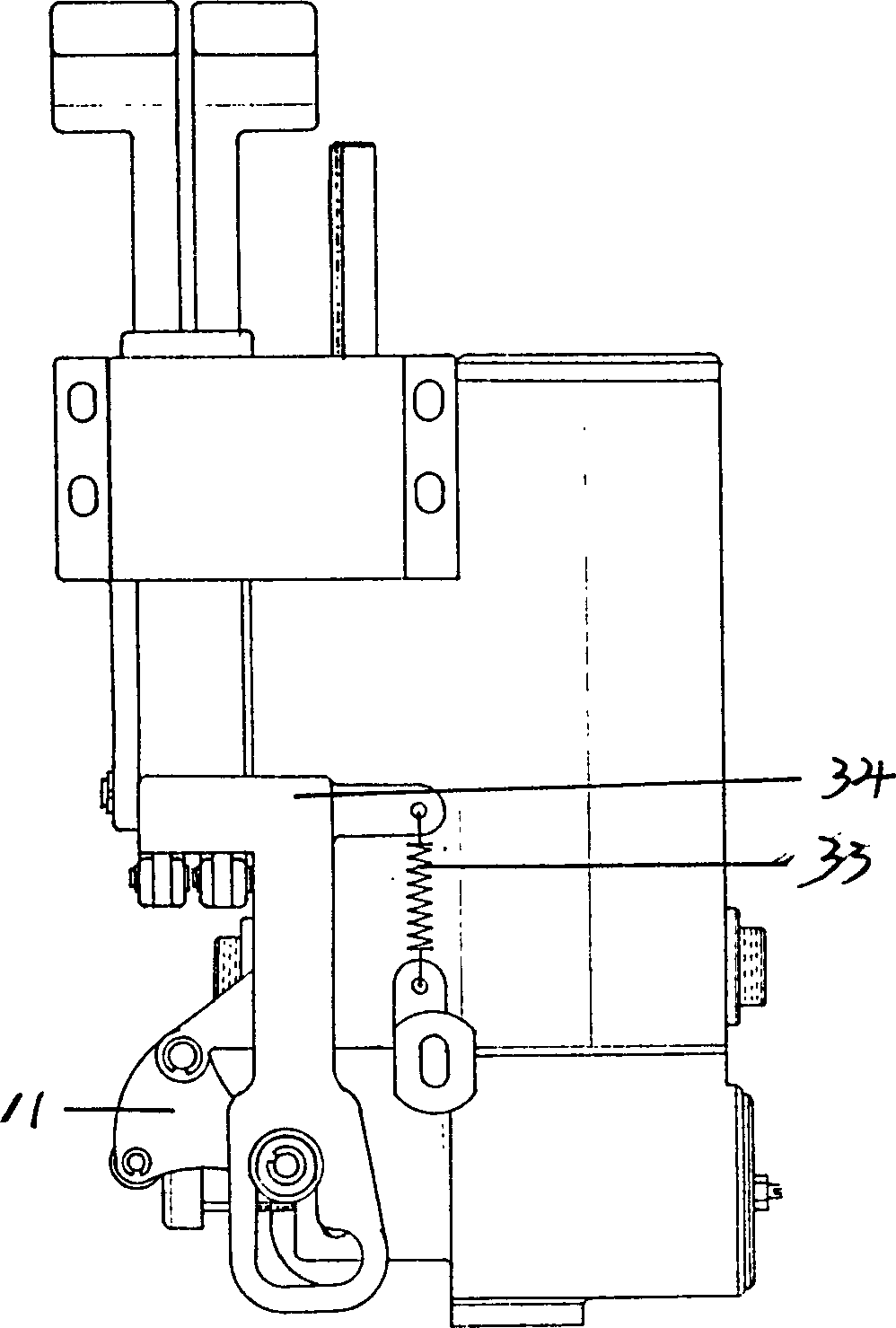
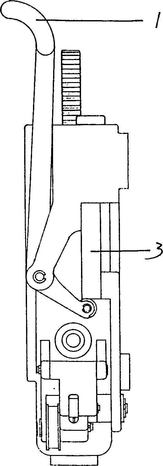
[0008] The implementation structure of the present invention specifically has: pressurized water tank 8 is equipped with plunger 2, has tooth on plunger 2, and the gear 4 on the same shaft with sector gear 5 engages, sector gear engages with rack 3, and rack has The toothed surface and the non-toothed surface are assembled together through the sealing cover 6, and a handle 1 is provided, the linkage device 34 is installed on the rack 3, the spring 33 is connected with the lever 11, and a check valve is installed at the water inlet of the pressurized water tank Check valve 9 is installed between 10 and water storage tank 31, if use clean water and reclaimed water simultaneously, check valve 27 storage tanks 31 can be provided, spring 30 can be arranged behind piston 28, be used to realize inversion. The delay valve part has a plunger 14, a spring cover 12 is installed, a spring 13 is arranged inside, a water inlet 26, a water outlet 16, a check valve 21, a rubber valve 24 are in...


PUM


Abstract

The invented boosting water tank is composed of a boosting water tank, a water storage tank and a time-delay valve, it is installed with handle and linkage device, a plugner is installed in the boosting water tank for increasing pressure, a regulating screw is installed on the time delay valve part for freely regulating the flushing time. The advatnages are that flushing time can be freely regulated according to actual using condition, to increas the flushing force.

Description

Technical field: [0001] The invention relates to a sanitary ware, which is a water tank used for flushing a toilet or a squatting pan, and is a water tank which can adjust the flushing time and increase the pressure. Background technique: [0002] The same type of water tank currently used cannot freely adjust the flushing time of the sleeve according to the actual use situation, and cannot increase the pressure additionally. Invention content: [0003] The invention provides a new type of water tank with adjustable flushing time and additional pressure. It has the following characteristics: it can be installed on sanitary ware such as toilet or squatting pan, and can be freely adjusted according to the actual use. Time, and additional pressure can be increased, and a piston can be installed in the water storage tank to realize inversion. [0004] In order to solve the problems existing in the prior art, the present invention adopts the following scheme to solve the probl...

Claims


Application Information

Patent Timeline
Patent Type & Authority Applications(China)
IPC IPC(8): E03D3/10
Inventor 陈国忠
Owner 陈国忠
Learn More