

Robot production system for cutting and marking line on profile steel
A production system and robot technology, which can be used in manipulators, program-controlled manipulators, metal processing machinery parts, etc., and can solve the problems of large floor space and long auxiliary time.
- Summary
- Abstract
- Description
- Claims
- Application Information
AI Technical Summary
Problems solved by technology
Method used
Image

Examples
Embodiment Construction
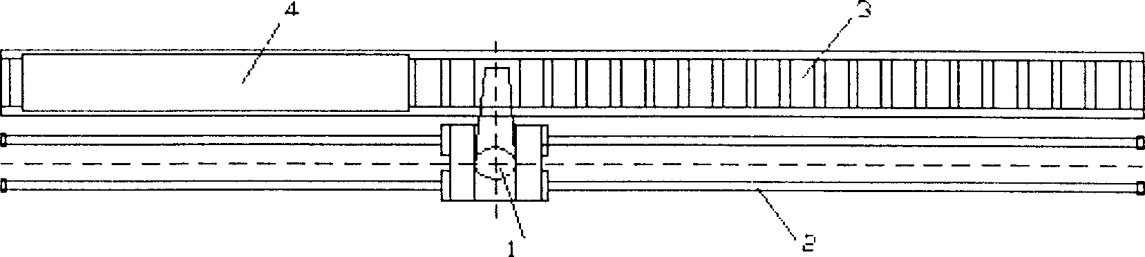
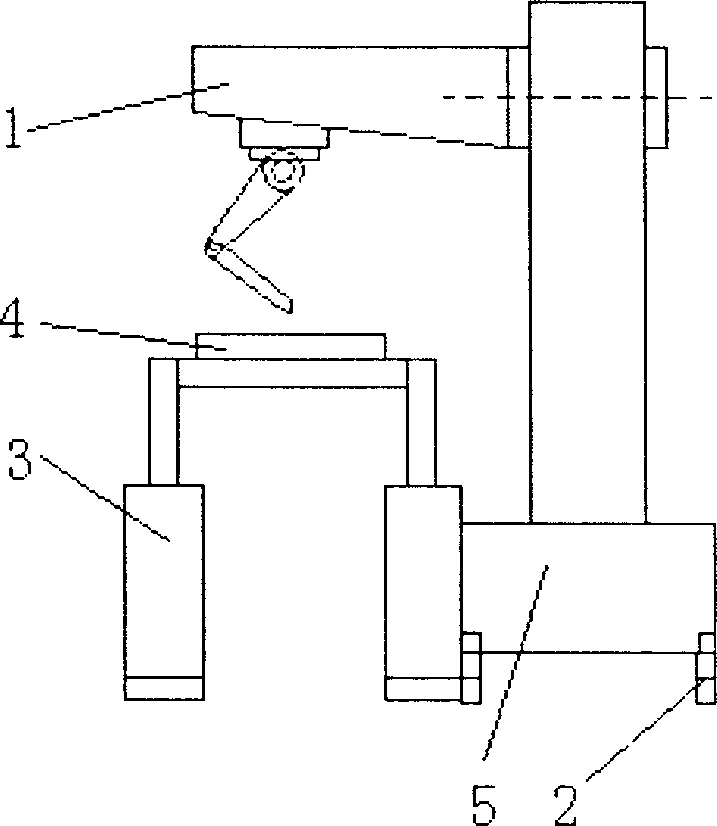
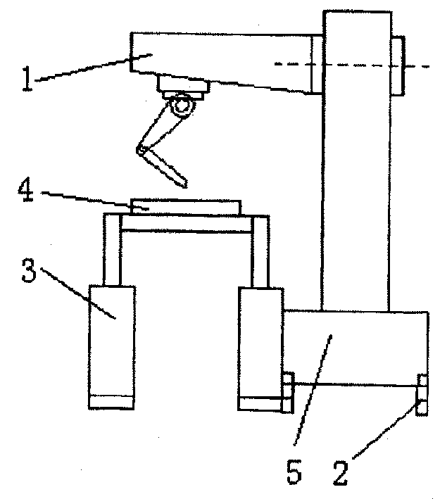
[0011] As shown in the figure, the production system of the present invention includes: a six-axis robot 1 and a workbench 3. During cutting and scribing, the six-axis robot 1 moves along the longitudinal direction of the section steel 4 placed on the workbench on its running track 2. Reciprocating work can be moved. The six-axis robot 1 moves on one side of the table to perform work. The workbench 3 in the production system is arranged as two vertical stations, one station is in cutting and scribing work, and the other station can carry out the operation process of section steel 4 input and output.
[0012] Workbench 3 is arranged as left and right stations, arranged in a straight line. On one side of the workbench 3, usually on the side of the non-people flow or logistics, a track 2 along the longitudinal direction of the workbench 3 is installed, a movable platform 5 is installed on the track 2, and a six-axis robot 1 is placed on the platform 5 . In this way, the six-ax...
PUM
 Abstract
Description
Claims
Application Information