
Mechanical centrifugal automatic clutch with high pulling torque

An automatic clutch, high torque technology, applied in the field of machinery, can solve problems such as unreliability, low efficiency and low torque

Inactive Publication Date: 2003-05-07
谭书渊
View PDF0 Cites 4 Cited by
  • Summary
  • Abstract
  • Description
  • Claims
  • Application Information

AI Technical Summary

Problems solved by technology

So far, ordinary mechanical centrifugal automatic clutches only use direct centrifugal force to control the combination or separation of friction pairs, so there are problems such as small torque, low efficiency, and unreliability, which limit its application range

Method used


Image

  • Mechanical centrifugal automatic clutch with high pulling torque
  • Mechanical centrifugal automatic clutch with high pulling torque

Examples


Embodiment Construction

[0010] Now in conjunction with the accompanying drawings, the structure, working principle, embodiment and effect of the present invention are described as follows:

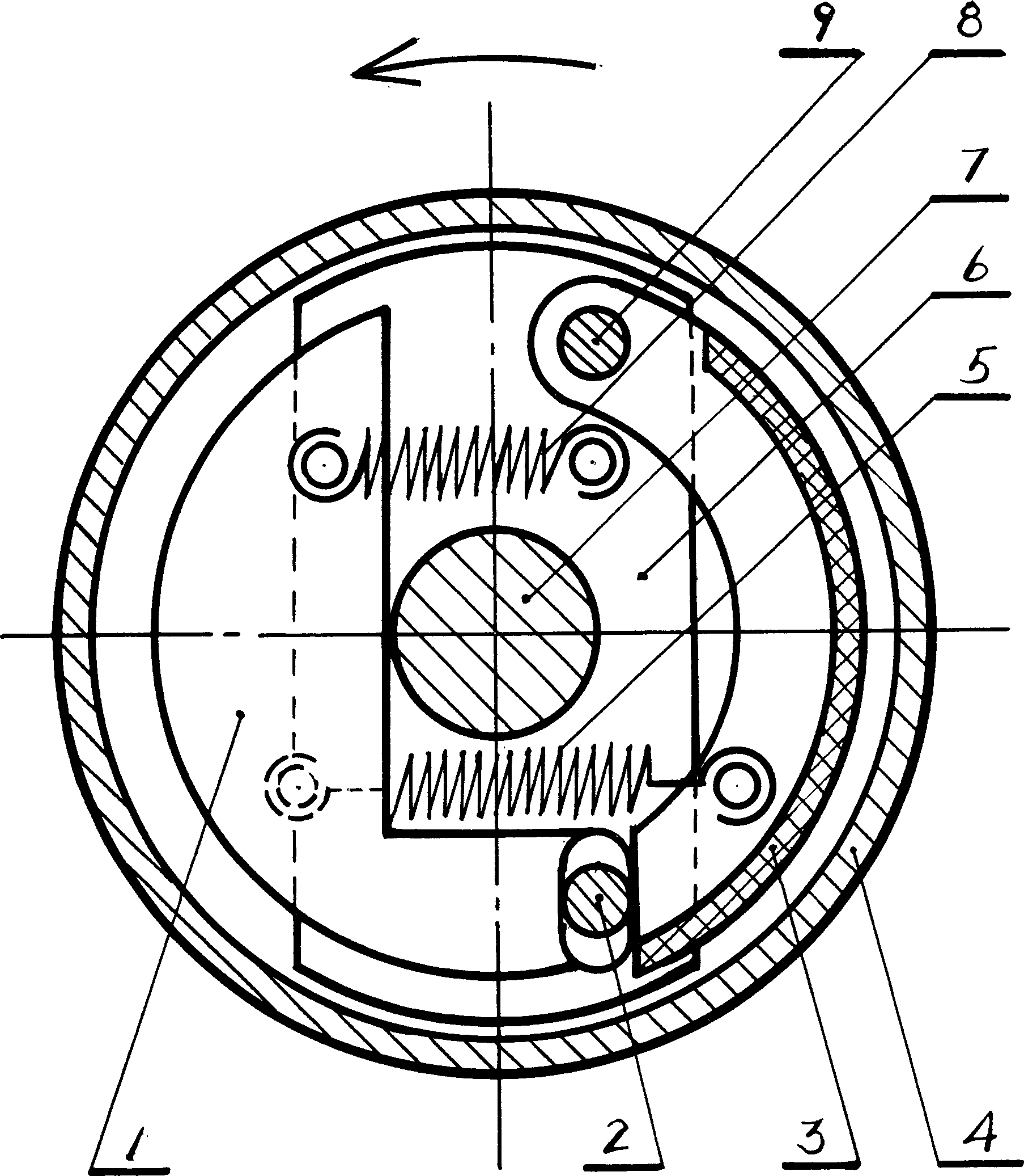
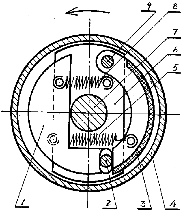
[0011] The structure of the automatic clutch includes: lever centrifugal block (1), fulcrum camshaft (2), friction block (3), transmission drum (4), return spring (5), bracket (6), main shaft (7) , memory spring (8), and pin shaft (9), wherein: the lever centrifugal block (1) and the fulcrum camshaft (2) are fixed as one, and memory spring (8), return spring (5), bracket ( 6), the main shaft (7), etc. constitute a lever centrifugal force amplifying device, which acts on the reliable combination and separation of the forced friction block (3) and the transmission drum (4).

[0012] Along with the rotation of the main shaft (7), the bracket (6) fixed on the main shaft (7) and the lever centrifugal block (1) supported on the bracket (6) by the fulcrum camshaft (2), and through the pin shaft ( 9) The friction blocks...


PUM


Abstract

This invention relates to a large torsion mechanical automatic centrifugal clutch using lever centrifugal amplifying theory, applying cam structure firstly to act the centrifugal force on lever then the lever amplifies the limited centrifugal force by times to turn it to a powerful lever force, and force a friction block and driving drum to combine and separate to greatly increase the centrifugal control force, greatly increase driving torsion and efficiency.

Description

technical field [0001] The invention relates to a centrifugal high-torque automatic clutch in the mechanical field. Background technique [0002] Ordinary mechanical centrifugal automatic clutches are widely used in small power and small torque matching occasions because of their simple structure and low cost. Such as Suzuki FR50 type automatic clutch, Honda C50 type automatic clutch, the most typical is the clutch of Yamaha MATE50 type automatic shifting. (Dai Wenwei et al. Imported motorcycle structure and maintenance technology. Guangdong: Science and Technology Press. 1984) [0003] For a long time, companies such as Yamaha in Japan have made unremitting efforts to make the small-torque automatic clutch that can only be used on 50-type motorcycles successfully applied to 125 women's motorcycles today. Although the torque has been improved by improving the process, it still cannot meet the high torque requirements of 250 motorcycles, and it is far from satisfying the hi...

Claims


Application Information

Patent Timeline
Patent Type & Authority Applications(China)
IPC IPC(8): F16D43/14
CPCF16D43/18F16D2043/145
Inventor 谭书渊
Owner 谭书渊
Learn More