
Hydraulic transmission machine

A kind of transmission machine and hydraulic technology, which is applied in the direction of transmission device, fluid transmission device, mechanical equipment, etc., can solve the problems of consumption, electric energy demand, increase production cost, etc., and achieve the effect of reducing volume and wide application

Inactive Publication Date: 2003-05-14
毛同岩
View PDF0 Cites 1 Cited by
  • Summary
  • Abstract
  • Description
  • Claims
  • Application Information

AI Technical Summary

Problems solved by technology

With the continuous change of the output torque, accompanied by the continuous increase of the power of the motor, the demand for electric energy and a large amount of consumption are caused, and the production cost of the enterprise is increased.

Method used


Image

  • Hydraulic transmission machine
  • Hydraulic transmission machine
  • Hydraulic transmission machine

Examples


Embodiment Construction

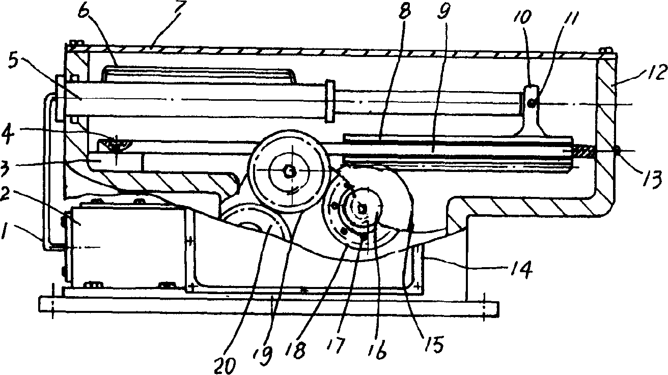
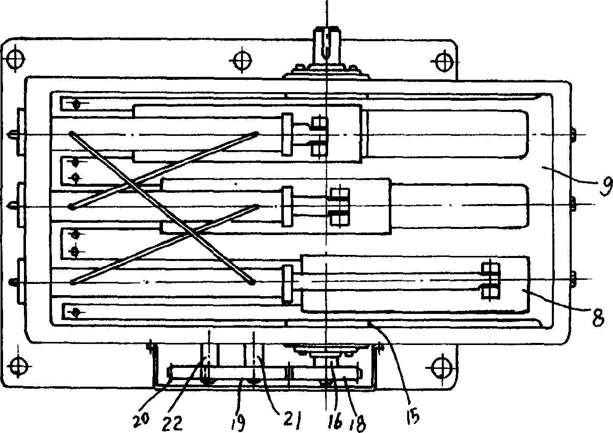
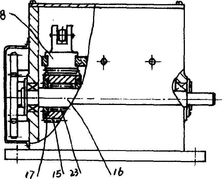
[0017] Depend on figure 1 , 2 The shown hydraulic transmission machine adopts the chassis 12 of the transmission machine, and three oil cylinders 5 arranged in parallel are fixedly arranged on the box wall at one end of the longitudinal direction in the chassis 12, and oil pipes 6 are connected to the top of the oil cylinders 5. Make each oil pipe 6 communicate with the configured oil cylinder 5 respectively, through the front end of the piston rod of the oil cylinder 5, use the hinge shaft 11 to be hinged to a hinge seat 10 on the upper end of the slider rack 8, the slider tooth In the groove slideway that the both sides of bar 8 have, configuration is provided with the slideway guide rail 9 that is fixed with cabinet 12, makes the slideway guiderail 9 two ends be respectively fixed on the side wall and the protrusion of cabinet 12 by screws 4 and 13. platform 3, so as to ensure that the slider rack 8 makes a horizontal linear displacement along the slideway guide rail 9. T...


PUM


Abstract

The hydraulic transmission machine consists of oil cylinders arranged parallelly in the longitudinal chassis, block racks connected to the front ends of all the piston rods, slide tracks integrated with the chassis inside the notches beside the block racks, transmission shaft set in the transverse direction of the chassis, friction type intermittent mechanism on the transmission shaft to mesh with the block racks, gear mechanism and distributor to connect the fore said parts. The present invention has power saving and reduced volume and may be used in low rotation and great torque transmission.

Description

technical field [0001] The invention relates to a driving machine, in particular to a stepless speed regulating hydraulic transmission equipment. Background technique [0002] At present, in the machinery industry, it is usually used as a high-power, low-speed, high-torque transmission mechanical equipment such as a large gear reducer. It uses a high-power motor to output power by driving a multi-stage gear mechanism. With the continuous change of the output torque, accompanied by the continuous increase of the power of the motor, the demand for electric energy and a large amount of consumption are caused, which increases the production cost of the enterprise. Contents of the invention [0003] The purpose of the present invention is to solve the problems of the above-mentioned technologies, and provide a hydraulic transmission machine that can realize low speed, high torque, overload self-protection, and continuous work through hydraulic drive. [0004] In order to achie...

Claims


Application Information

Patent Timeline
Patent Type & Authority Applications(China)
IPC IPC(8): F16H47/02
Inventor 李增丽
Owner 毛同岩
Learn More