Circuit for raising unbalance of multi-output power source loads

An unbalanced load and multi-output technology, which is applied in the direction of output power conversion device, DC power input conversion to DC power output, electrical components, etc., can solve the problems of increasing circuit complexity and unbalanced multi-output power supply load. , to achieve the effect of reducing the load imbalance

Inactive Publication Date: 2003-05-14
ZTE CORP
View PDF2 Cites 9 Cited by
  • Summary
  • Abstract
  • Description
  • Claims
  • Application Information

AI Technical Summary

Problems solved by technology

[0016] The technical problem to be solved by the present invention is to further improve the load unbalanc

Method used


Image

  • Circuit for raising unbalance of multi-output power source loads
  • Circuit for raising unbalance of multi-output power source loads
  • Circuit for raising unbalance of multi-output power source loads

Examples


Example Embodiment

[0041] The present invention will be further described in detail below with reference to the accompanying drawings and embodiments. The following analysis ignores the line voltage drop and the conduction voltage drop of the electronic switch.
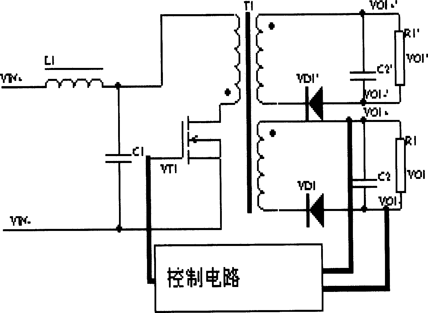
[0042] figure 1 , figure 2 This has been described in detail in the Background section.

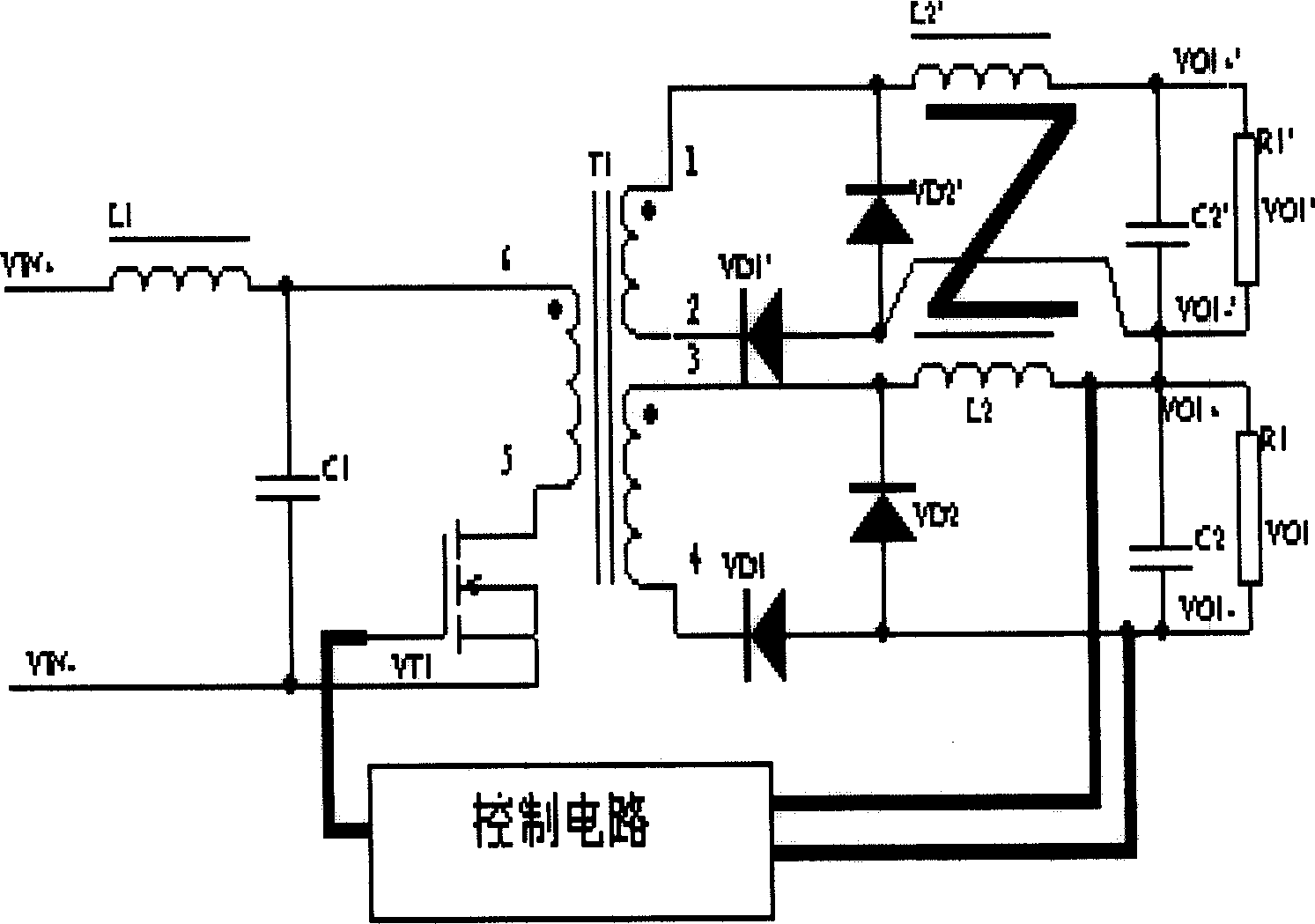
[0043] image 3 It is a schematic diagram of the first technical solution of the present invention.

[0044] The positive electrode of the input voltage forms a series loop with the first inductor L1, the primary side of the transformer, the MOSFET, and the negative electrode of the input voltage. The first capacitor C1 is connected across the connection point between the first inductor L1 and the primary side of the transformer and the negative electrode of the input voltage. The pole is connected in series with the transformer, the MOSFET source is connected with the negative input, and the negative pole of the first capacitor C1 is connected...


PUM


Abstract

The present invention relates to switching power supply and is circuit for reducing unbalance of multi-output power source loads. The technological scheme includes the positive pole of input voltage,L1, transformer primary side, MOSFET and the negative pole of input voltage constitute one serial loop; C1 is connected across the joint of L1 and transformer primary side and input voltage negative pole; MOSFET has its drain connected serially with the transformer and source connected to input voltage negative pole and C1 is connected to the input voltage negative pole; two transformer secondarywindings separates the output circuit into two braches, I and II; and the control circuit has input from the output of branch I and produces drive puls as the drive signal of MOSFET in transformer primary side and connected to the grid of MOSFET.

Description

technical field [0001] The invention relates to the field of switching power supplies, in particular to the field of secondary power supplies with single-channel control and multiple outputs. Background technique [0002] Multiple output power supplies are used in many occasions, but how to ensure that each output voltage accuracy is high, or the load imbalance (LOAD CROSS-REGULATION) is high, there are many specific solutions, which can be summarized into the following two Type: 1) Feedback control is performed on one channel, or a set of feedback circuits is used to control multiple channels at the same time, and then the winding coupling degree is increased. For example, US Patent No. 5,930,124 "Switching power supply" is to increase the coupling degree of the windings greatly by adding capacitors in series between the windings of the transformer. The essence of this scheme is to increase the coupling between windings or inductances on the basis of ordinary forward or fl...

Claims


Application Information

Patent Timeline
IPC IPC(8): H02M3/335
Inventor 高晓光
Owner ZTE CORP
Why Eureka
Try Eureka