
Driving gear for stepless speed change device for motor cycle

A continuously variable speed, driving wheel technology, applied in the direction of vehicle gearbox, vehicle components, chain/belt transmission, etc., can solve the problems of large change in speed ratio, low transmission efficiency, poor riding comfort and sliding performance, etc. The effect of reducing noise and wear, improving transmission efficiency and driving comfort

Inactive Publication Date: 2003-05-21
程吾
View PDF0 Cites 7 Cited by
  • Summary
  • Abstract
  • Description
  • Claims
  • Application Information

AI Technical Summary

Problems solved by technology

[0003] 1. When the motorcycle starts and runs at low speed, the centrifugal force of the centrifugal roller is small, the inclined plate presses the moving wheel to move axially, the diameter of the belt on the driving wheel is small, and the transmission efficiency is low
If the centrifugal force of the centrifugal roller is increased by increasing the weight of the centrifugal roller, the wear of the centrifugal roller will be large, which will obviously reduce the service life of the continuously variable transmission driving wheel of the motorcycle
[0004] 2. When the motorcycle loosens the throttle, the wheel diameter of the belt on the driving wheel suddenly becomes smaller, which makes the motorcycle stop, and the riding comfort and sliding performance are poor.
[0005] 3. When the motorcycle is running at medium-to-high-end and low-fuel, when it needs to accelerate quickly, the transmission ratio changes slowly, the speed ratio changes greatly, and the engine resistance is large

Method used


Image

  • Driving gear for stepless speed change device for motor cycle
  • Driving gear for stepless speed change device for motor cycle
  • Driving gear for stepless speed change device for motor cycle

Examples


Embodiment Construction

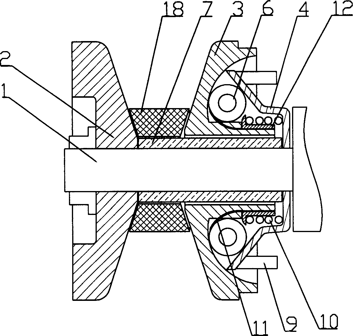
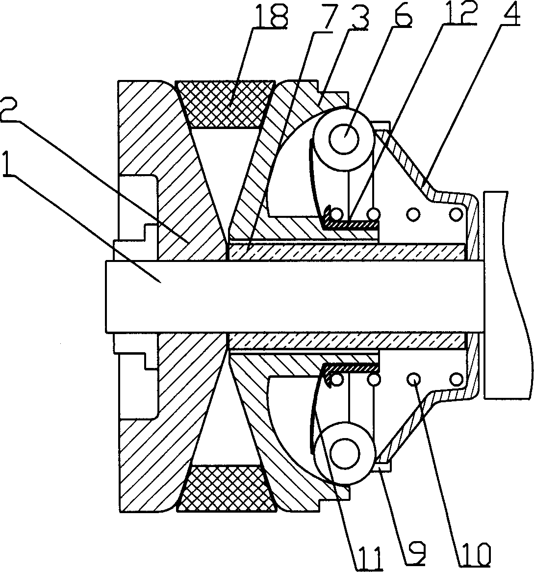
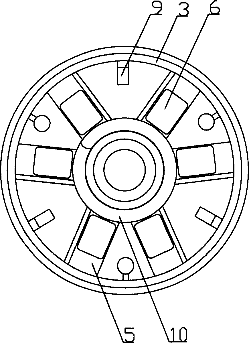
[0025] figure 1 , figure 2 , image 3 , Pic 4-1 , Figure 4-2 Example 1 of the present invention is given. The continuously variable transmission driving wheel of the motorcycle of the present embodiment comprises: an engine main shaft 1, which is provided with a fixed wheel 2, a moving wheel 3 and a slope plate 4, and a belt 18 is provided between the fixed wheel and the moving wheel. The moving wheel is provided with a centrifugal roller groove 5 and a centrifugal roller 6, and the moving wheel 3 can move axially on the sliding sleeve 7 of the engine main shaft. The fixed wheel 2, the moving wheel 3, the ramp plate 4 and the engine main shaft 1 rotate synchronously; the ramp plate 4 is provided with a driving groove 8, and the moving wheel is provided with a driving guide post 9 corresponding to the driving groove. Stage clip 10 is provided between moving wheel and ramp plate. An elastic dial 11 is arranged in the centrifugal roller channel. Stage clip is provided w...


PUM


Abstract

The stepless speed change driving wheel for motorcycle includes engine main shaft, on the engine main shaft a fixed wheel, a moving wheel and a slop board are set, in the moving wheel a centrifugal roller conduit and centrifugal roller are set, the moving wheel can be axially moved mo the sliding bush of engine main shaft, the fixed wheel and engine main shaft can be synchronsouly rotated, between the moving wheel and engine main shaft a driving mechanism is set, and between the moving wheel and slop board an elastic component, said elastric component adopts spreader spring perfectly, so thatthe rotating speed and torque of driven wheel can obtain more reasonable distribution. As compared with existent motorcycle it can save fuel by about 20%.

Description

Technical field: [0001] The invention relates to the field of continuously variable transmission devices for motorcycles, in particular to a continuously variable transmission driving wheel for motorcycles. Background technique: [0002] The general structure of the driving wheel of the existing continuously variable transmission motorcycle is: the engine main shaft is provided with a fixed wheel, a moving wheel and a slope plate, and the moving wheel is provided with a centrifugal roller groove and a centrifugal roller; Move up the axis. When the main shaft of the engine rotates, the centrifugal roller in the moving wheel generates centrifugal force to push the moving wheel to move axially, so that the diameter of the belt on the driving wheel changes, thereby changing the speed and output torque of the driven wheel. There is following deficiency in this kind motorcycle continuously variable speed driving wheel: [0003] 1. When the motorcycle starts and runs at a low spe...

Claims


Application Information

Patent Timeline
IPC IPC(8): B62M9/08
Inventor 程吾
Owner 程吾
Learn More