Weft knitting machine with transferring mechanism and transferring method

A technology of stitch transfer and flat knitting, which can be used in flat knitting with separate action needles, textile and paper making, weft knitting, etc., and can solve problems such as thread breakage

Inactive Publication Date: 2003-05-28
SHIMA SEIKI MFG LTD
View PDF2 Cites 6 Cited by
  • Summary
  • Abstract
  • Description
  • Claims
  • Application Information

AI Technical Summary

Problems solved by technology

The space for needle entry can be enlarged by increasing the thickness of the stitch junction in the height direction, but when knitting with thin stitches, the burden is placed on the stitches and there is a risk of thread breakage

Method used


Image

  • Weft knitting machine with transferring mechanism and transferring method
  • Weft knitting machine with transferring mechanism and transferring method
  • Weft knitting machine with transferring mechanism and transferring method

Examples


Embodiment Construction

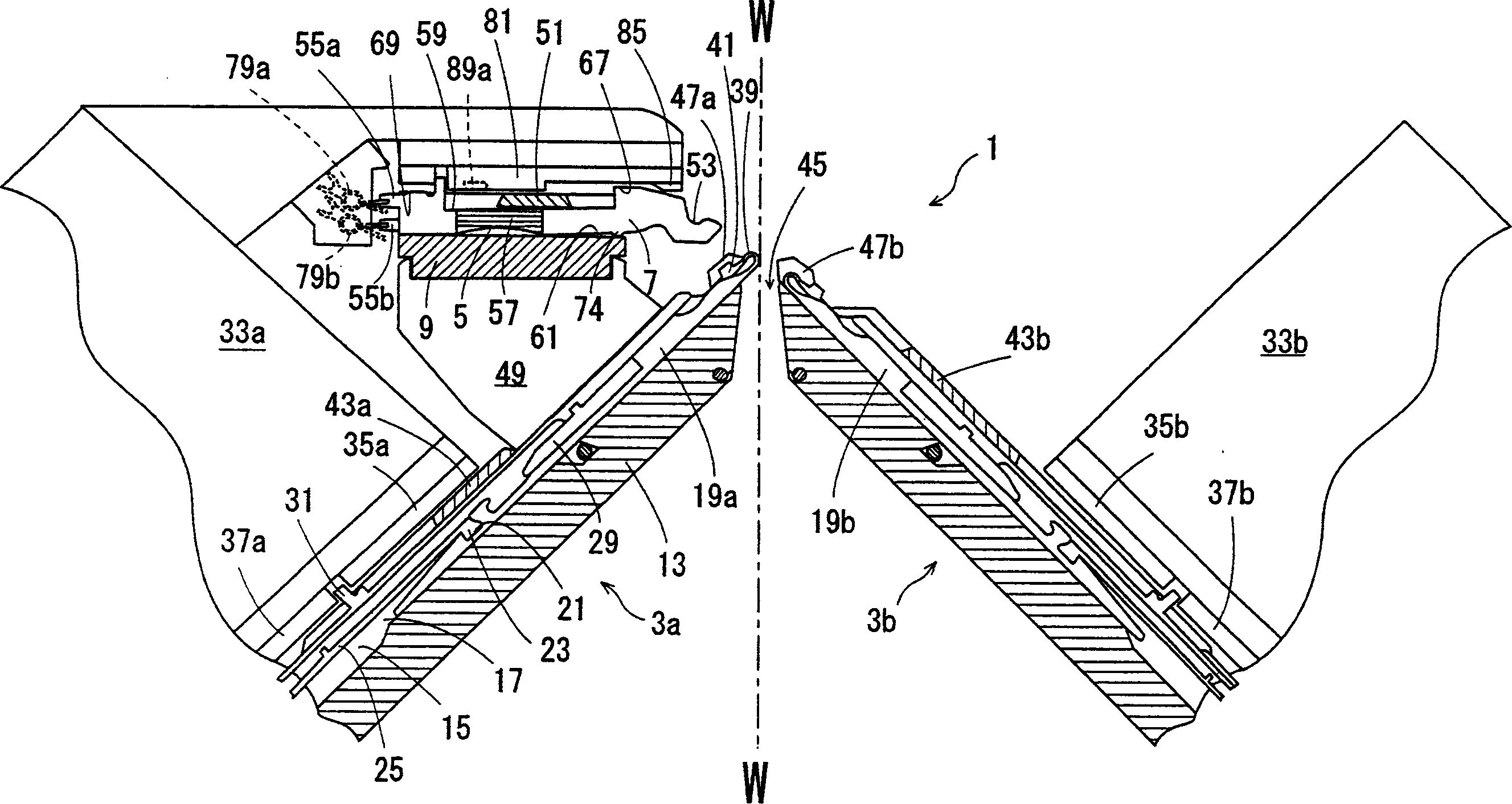
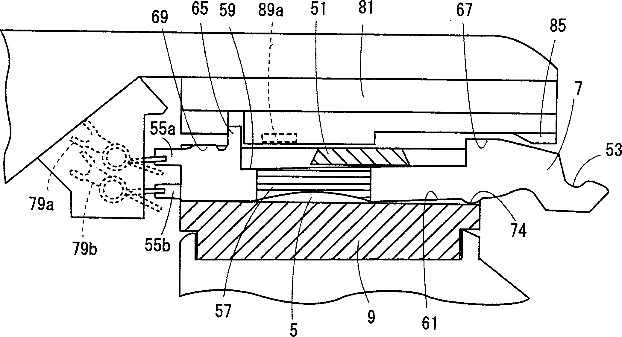
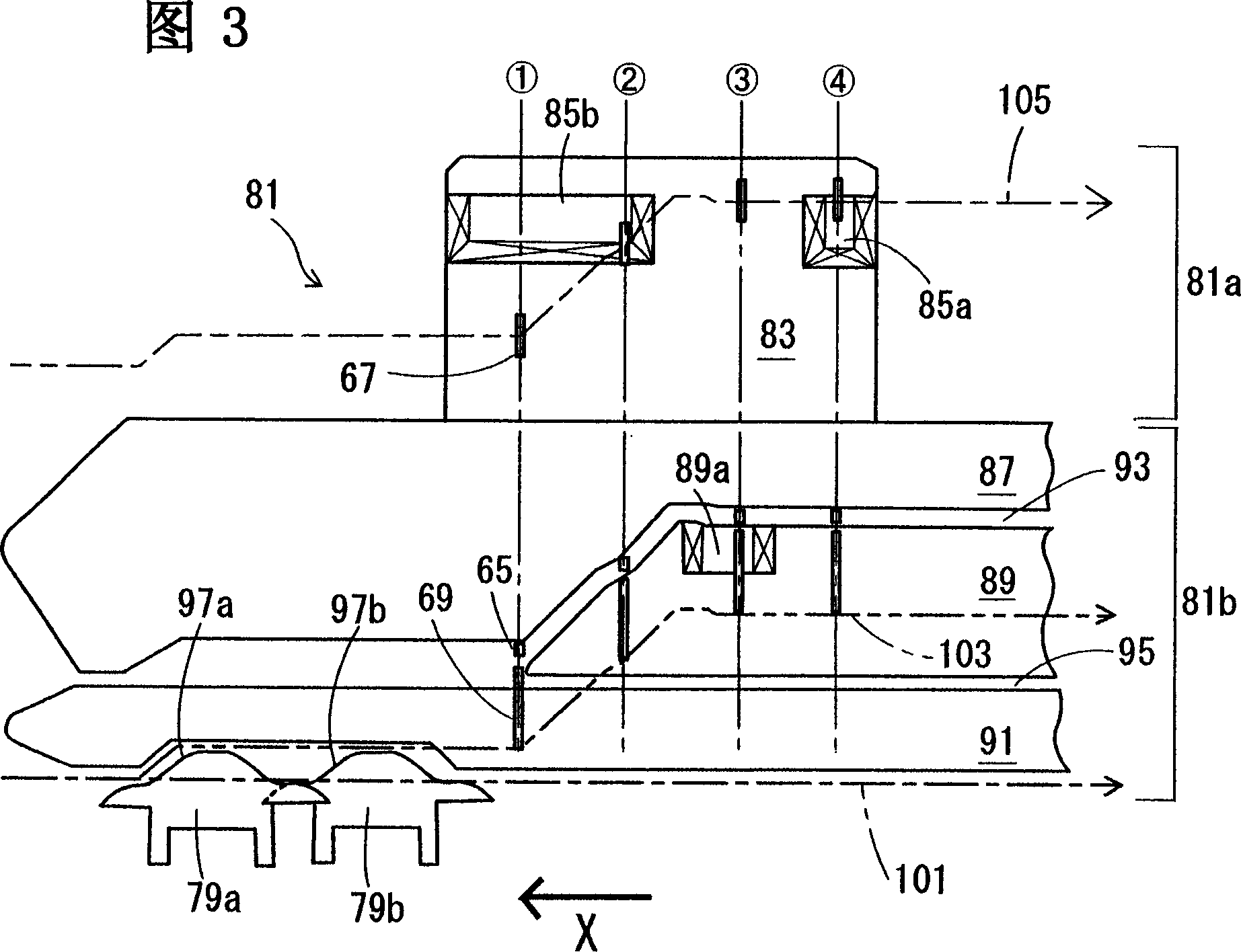
[0026] Examples of the present invention will be described. use figure 1 ~ Figure 3 illustrates the structure of the flat knitting machine. The flat knitting machine has a pair of front and back lower needle beds 3a, 3b arranged opposite to each other, and a TR foot piece groove 5 formed on the top of the front lower needle bed (hereinafter referred to as the front bed 3a) to hold the TR. TR footer bed 9 for footer 7. In the lower needle beds 3a and 3b, needle plates 17 are erected in the grooves formed on the needle bed base plate 13, and needle grooves 15 are formed between adjacent needle plates 17, 17. The tooth mouth central line W-W between the beds can move forward and backward to keep the needle 19. The rear needle bed 3b (hereinafter referred to as the rear bed 3b) is driven by a driving device not shown to be movable in the longitudinal direction of the needle bed (hereinafter referred to as a pushing operation).

[0027]In this embodiment, the needle 19 installe...


PUM


Abstract

A weft knitting machine, comprising a transfer jack bed (9) holding a transfer jack (7) so as to be movable forward and backward, wherein, when a transfer is made from the transfer jack (7) to a needle (19), a hook rear surface part (39b) of the needle (19) is advanced into a loop (111) locked to a loop locking part (53) of the transfer jack (7) after the loop locking part (53) of the transfer jack (7) located at an advanced position is lowered to a down position, and a hook front surface part (39a) of the needle is advanced into the loop after the loop locking part (53) is raised to an upper position, whereby the loop can be surely exchanged and the transfer capable of reducing a load on the loop can be made through a common route for the needles of a front bed (13a) and a rear bed (13b).

Description

technical field [0001] The invention relates to a flat knitting machine with a stitch transfer mechanism and a stitch transfer method. The stitch transfer mechanism has a stitch transfer bed (hereinafter referred to as a TR chassis bed) on a needle bed. There are many stitch-transfer stitches with stitch joints at the front ends, and the stitch-transfer mechanism is located between the TR stitches of the TR stitch bed and the needles of the needle bed. Background technique [0002] Japanese Patent Registration No. 2794144 discloses a flat knitting machine. The flat knitting machine holds a pair of front and rear needle beds formed by freely advancing and retreating needles in grooves formed on the top, and one or both needle beds are It is configured so that it can move left and right relative to the other needle bed, and at least one of the needle beds has a transfer shoe bed that holds the transfer shoe freely in a groove formed on the upper surface to move forward and bac...

Claims


Application Information

Patent Timeline
Patent Type & Authority Applications(China)
IPC IPC(8): D04B7/28D04B15/02
CPCD04B7/28D04B15/78D04B15/02D04B15/365D04B7/20
Inventor 森田敏明澁田武一
Owner SHIMA SEIKI MFG LTD
Why Eureka
Try Eureka