Disk driving device

A technology for a disk drive device and drive components, which is applied in the directions of driving/moving a recording head, recording information on a magnetic disk, and arranging/installing the recording head, etc., can solve the problems such as the inability to respond to the impact sensor and the difficulty in setting the head actuator.

Inactive Publication Date: 2003-06-11
KK TOSHIBA
View PDF0 Cites 0 Cited by
  • Summary
  • Abstract
  • Description
  • Claims
  • Application Information

AI Technical Summary

Problems solved by technology

However, it is difficult to set the position of the

Method used


Image

  • Disk driving device
  • Disk driving device
  • Disk driving device

Examples


Embodiment Construction

[0023] Referring now to the accompanying drawings, the magnetic disk device according to the embodiment of the present invention will be described in detail.

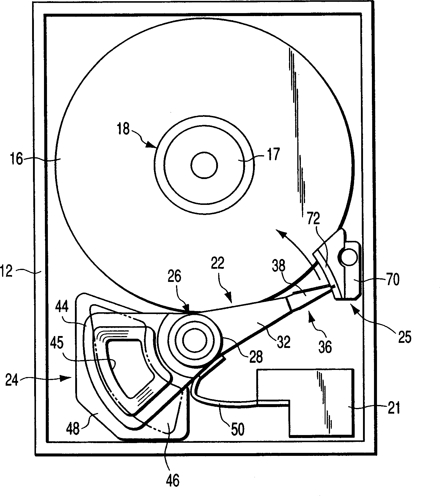
[0024] Such as figure 1 As shown, the HDD includes a housing 12 shaped like a rectangular box;

[0025] In the casing 12 are arranged a magnetic disk 16 serving as a magnetic recording medium; a spindle motor 18 as a driving tool for supporting and rotating the magnetic disk; magnetic heads for writing and reading information from the magnetic disk; and a head actuator 22 , which supports the movement of the head relative to the disk 16. Housing 12 also includes voice coil motor (referred to as VCM hereinafter) 24 for swinging and positioning head actuators; ramp loading mechanism 25 for clamping and positioning the magnetic head leaving the magnetic disk; Magnetic head ICs and the like.

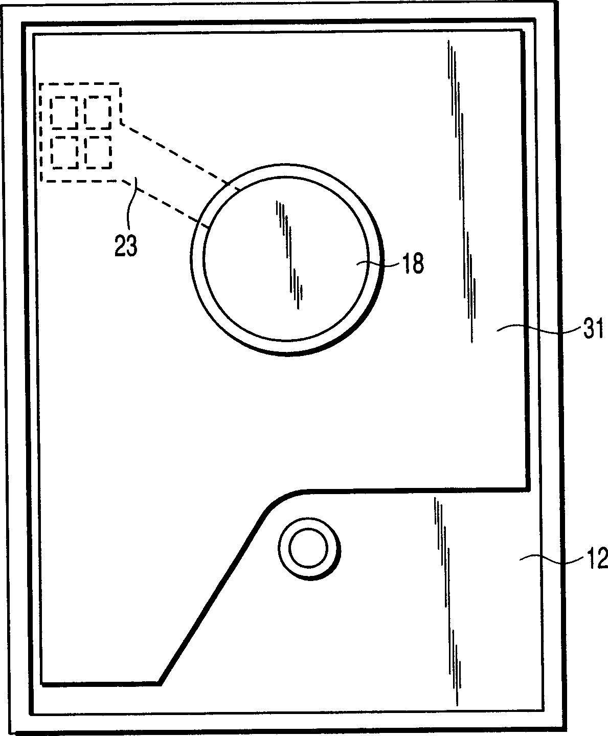
[0026] Such as figure 2 As shown, a printed circuit board 31 that controls the operation of the spindle motor 18 , VCM 24 , and...


PUM


Abstract

A disk drive apparatus includes a drive section, which has a disk, a motor for supporting and rotating the disk, a head configured to perform an information processing operation with respect to the disk, and a head actuator supporting the head for movement relative to the disk, and a shock sensor for detecting the respective levels of a shock and a vibration externally applied to the drive section. The apparatus includes a compensation filter for amplifying the shock and vibration levels in a frequency band corresponding to the resonance frequency of the drive section, out of the shock and vibration levels detected by means of the shock sensor. A control section stops the information processing operation of the head when given values are exceeded by the external shock and vibration levels detected by means of the shock sensor and inputted through the compensation filter.

Description

technical field [0001] The present invention relates to a disk drive equipped with a shock sensor. Background technique [0002] Optical discs and magnetic disk drives are widely used as record / replay devices for modern computers. For example, a hard disk drive (hereinafter referred to as HDD) generally includes a magnetic disk, which is provided in a housing; a spindle motor for supporting and rotating the magnetic disk; a rotary head actuator for supporting the magnetic head; and a voice coil motor for driving the head actuator. ; Substrate components, etc. In addition, a printed circuit board for controlling the operation of the HDD is provided on the outer surface of the bottom wall of the casing. [0003] The head actuator is provided with a bearing portion, which is mounted to the housing, from which arms protrude, and from which suspensions protrude respectively. The magnetic heads are respectively mounted on corresponding extension ends of the suspension. The voi...

Claims


Application Information

Patent Timeline
IPC IPC(8): G11B33/14G11B5/54G11B5/55G11B19/04G11B21/08G11B21/10G11B33/08
CPCG11B19/04G11B5/5582G11B5/54G11B33/08
Inventor 上松昌哉
Owner KK TOSHIBA
Why Eureka
Try Eureka