Buttonhole stitching machine

A sewing machine and buttonhole technology, which is applied to sewing machine components, sewing machine needle holders, and program-controlled sewing machines, etc., can solve the problems of fabric floating and fabric deviating from the original position, and achieve reliable cutting, preventing movement, and suppressing poor cutting. Effect

Inactive Publication Date: 2003-06-18
JUKI CORP
View PDF0 Cites 7 Cited by
  • Summary
  • Abstract
  • Description
  • Claims
  • Application Information

AI Technical Summary

Problems solved by technology

[0007] However, in the conventional buttonhole sewing machine, when the lower thread and core thread are cut, the presser foot rise

Method used


Image

  • Buttonhole stitching machine
  • Buttonhole stitching machine
  • Buttonhole stitching machine

Examples


Embodiment Construction

[0027] Hereinafter, specific embodiments of the present invention will be described with reference to the drawings. However, the scope of the present invention is not limited to the examples shown in the drawings.

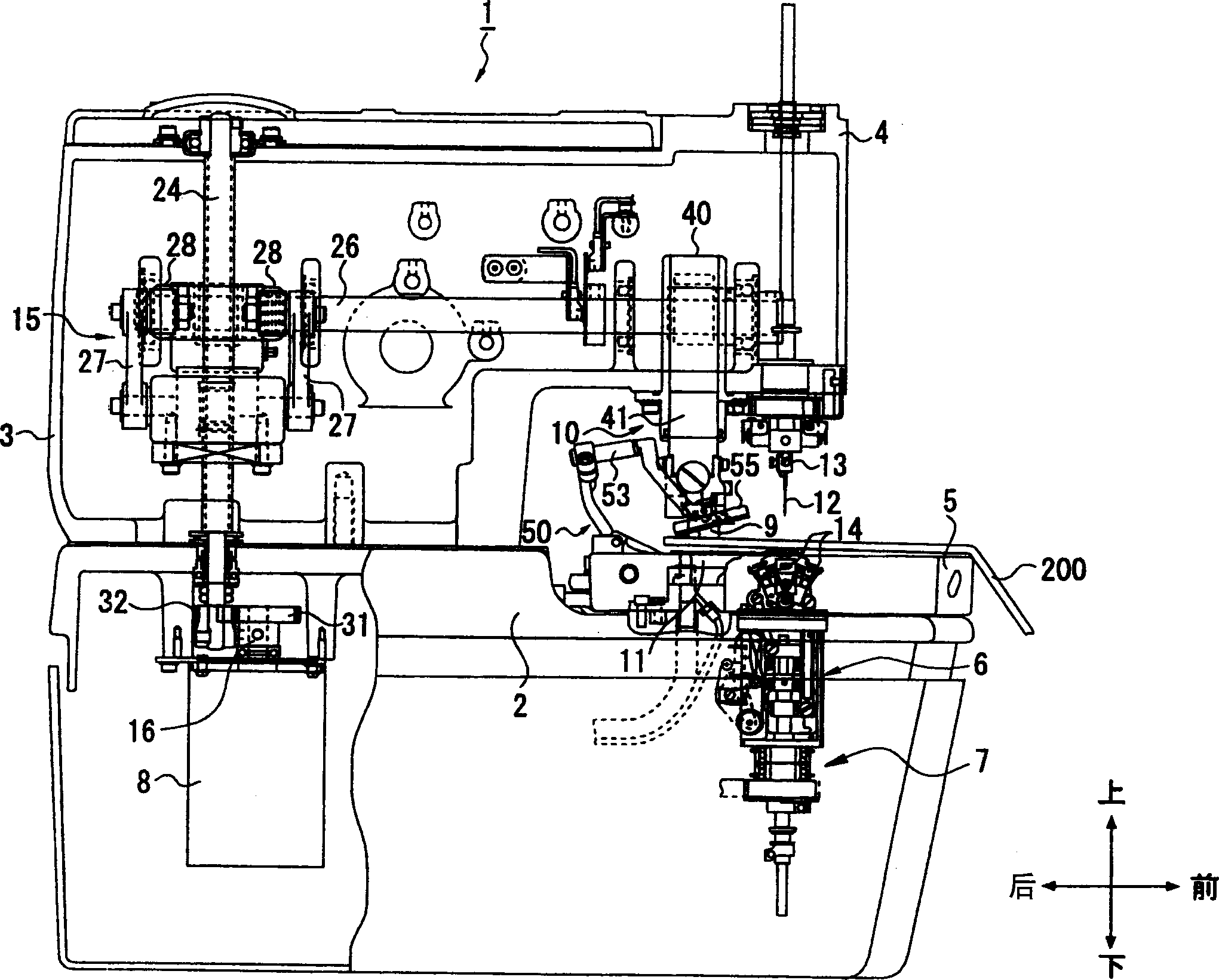
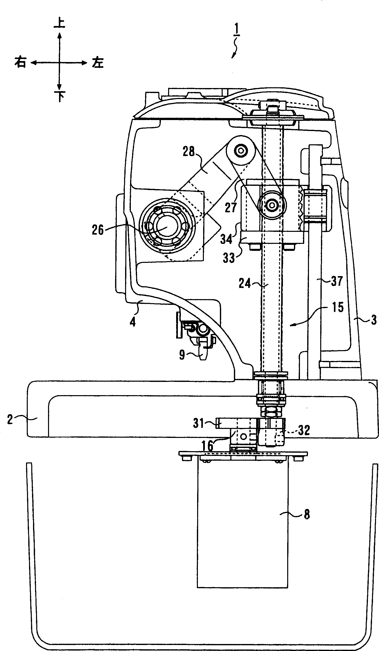
[0028] Such as figure 1 As shown, the buttonhole sewing machine 1 applying the present invention has: a machine base 2, a vertical body portion 3 arranged upright on the rear end portion of the machine base 2, and a vertical body portion 3 from the top of the vertical body portion 3 to the machine base portion 2. The machine head 4 that extends slightly in parallel, the needle bar 13 that extends downward from the front end of the machine head 4, the machine needle 12 that is installed on the lower end of the needle bar 13, and the machine needle 12 that is located in the machine table part 2. The rotary hook mechanism 6 below, the overall control device 100 for controlling the sewing machine 1 (such as Figure 4 shown), an operation panel 106 for inputting data ...


PUM


Abstract

An eyelet buttonholing machine 1 is provided with freely vertically movable cloth pressers 55 and 56, a knife receiver 9 freely movable between an elevated position and a cutting position, a cloth cutting knife 11, an upper knife 61 and a lower knife 62 provided on a feed plate 58, an air cylinder 65 driving the upper knife 61 and the lower knife 62 from an opening position to a closing position, a presser driving cylinder 59 vertically driving the cloth pressers 55 and 56, a cloth cutting motor 8 vertically driving the knife receiver 9, and a controller 100 controlling the cloth cutting motor 8, the air cylinder 65 and the presser driving cylinder 59. After the cloth pressers 55 and 56 are elevated after sewing and eyelet hole formation, when the knife receiver 9 is positioned at a prescribed height between the elevated position and the cutting position, the controller 100 operates the air cylinder 65 and the upper knife 61 and the lower knife 62 are moved to the closing position. The invention is to shorten the remaining lengths of a bobbin thread and a core thread and to surely cut the bobbin thread and the core thread.

Description

technical field [0001] The present invention relates to a buttonhole sewing machine for forming buttonholes on cloth and applying lockstitches around the buttonholes before or after the buttonholes are formed. Background technique [0002] A buttonhole sewing machine forms buttonholes called eyelets on a cloth placed on a cloth feed table, and applies lock seams around the eyelets before or after forming the eyelets. [0003] On this sewing machine, the upper and lower threads are used to form overlock stitches on the fabric by the action of the rotary hook that moves in conjunction with the up and down motion and swing motion of the machine needle. Also, a thick thread called a core is sometimes sewn into this stitch. And the cloth cutting knife descends from the top of the cloth to the cloth, and the cloth cutting knife aligns with and overlaps with the knife bearing platform arranged below the cloth, thus forming a round buttonhole on the cloth. In addition, in order to...

Claims


Application Information

Patent Timeline
IPC IPC(8): D05B3/08D05B3/06D05B19/12D05B37/02D05B65/00
CPCD05B3/08D05B19/14D05B29/02D05B37/04D05B55/14D05B65/02D05B69/30
Inventor 日塔隆
Owner JUKI CORP
Why Eureka
Try Eureka