Vertical preflex device for rib cold bending unit

A technology of cold bending machine and rib, applied in the directions of transportation and packaging, hull parts, hull, etc., can solve the problems of troublesome operation, complicated mechanism, difficult maintenance, etc., and achieve the effect of simple mechanism

Inactive Publication Date: 2003-06-25
WUHAN UNIV OF TECH
View PDF0 Cites 4 Cited by
  • Summary
  • Abstract
  • Description
  • Claims
  • Application Information

AI Technical Summary

Problems solved by technology

Correcting the "side bend" by adding gaskets has the disadvantage that the gaskets are pulled by friction, easily damaged, and the operation is troublesome; in addition, such as the Swiss rib cold bending machine, in the lower part of the complex middle frame, The mechanism of vertical bending oil cylinder is set to level the ribs. The mechanism of this method is complicated and has the disadvantage of difficult maintenance

Method used


Image

  • Vertical preflex device for rib cold bending unit
  • Vertical preflex device for rib cold bending unit

Examples


Embodiment Construction

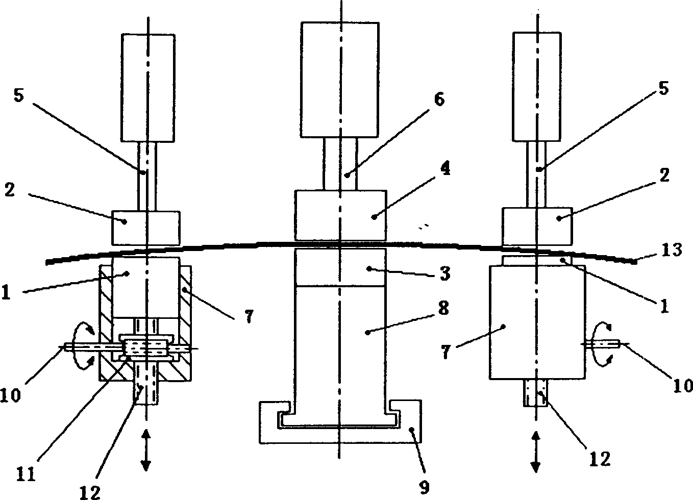
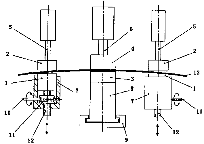
[0012] Below in conjunction with accompanying drawing and embodiment the present invention is described in further detail:

[0013] figure 1 The vertical pre-bending device of the rib cold bending machine shown includes the side lower chuck 1 installed on the side frame 7 of the cold bender, the side upper chuck 2 driven by the side clamping cylinder 5, and the middle frame 8 The middle and lower chuck 3, the middle and upper chuck 4 driven by the middle clamping cylinder 6, and the worm 10, worm wheel 11, and side lower chuck support screw 12 that can drive the side lower chuck 1 to move up and down, as for the worm 10 can utilize hand wheel, electric motor or hydraulic motor etc. to drive and rotate.

[0014] The vertical pre-bending device of this rib cold bending machine: the worm 10 on the side frame 7 is driven to rotate by means of a hand wheel, an electric motor or a hydraulic motor, and the worm 10 drives the worm wheel 11 to rotate, and the worm wheel 11 and the sid...


PUM


Abstract

The present invention relates to vertical preflex unit for rib cold bending machine. It has one combined driving mechanism comprising worm, worm gear and side lower chuck supporting screw to realize the vertical motion of the side lower chucks. There is some height difference between the clamping plane of the side lower chucks and the clamping plane of the middle lower chuck. When the rib shape is clamped, some vertical preflex is formed between each of the side chucks and the middle chuck, and this can eliminate the "side bending" phenomenon produced during bending rib. The present invention is used in ship yard for machining rib, cross beam, longitudinal keel and other curved members.

Description

technical field [0001] The invention relates to shipbuilding equipment, in particular to a vertical pre-bending device for a rib cold-bending machine for processing components with curved shapes on ships. Background technique [0002] Most of the hull ribs are asymmetric profiles. When the three fulcrums are bent, they are generally clamped by the chucks of the two sides of the frame. Through the forward and backward movement of the middle frame and its chucks on the track, the force is exerted in the front (rear) direction. Bending force, that is, horizontal bending of the profile. However, after the profile bends and springs back, in addition to obtaining the bending deformation in the horizontal direction, it also produces unnecessary bending deformation in the vertical direction, which is usually called "side bending". [0003] In order to eliminate this unnecessary "side bending" deformation, generally there is a certain height difference between the lower clamps on bo...

Claims


Application Information

Patent Timeline
Patent Type & Authority Applications(China)
IPC IPC(8): B21D11/00B63B3/26
Inventor 王呈方茅云生冷荣嘉向祖权
Owner WUHAN UNIV OF TECH
Why Eureka
Try Eureka