
Coil spring contact type connector

A coil spring, connector technology, applied in the direction of clamping/spring connection, connection, conductive connection, etc.

Inactive Publication Date: 2003-06-25
YOKOWO CO LTD
View PDF0 Cites 8 Cited by
  • Summary
  • Abstract
  • Description
  • Claims
  • Application Information

AI Technical Summary

Problems solved by technology

[0007] However, in the conventional coil spring contact connector as described above, since the connection spring coil is elastically deformed obliquely to the axial direction during connection, the connection electrode is affected by the pressure of the connection spring coil against the connection electrode. Changes in the contact position in the direction of the axis connecting the spring coils
Therefore, there are problems in the accuracy of the contact position of the connection spring coil 70 for the predetermined connection electrodes 8c, 9c and the stability of the contact state.

Method used


Image

  • Coil spring contact type connector
  • Coil spring contact type connector
  • Coil spring contact type connector

Examples


Embodiment Construction

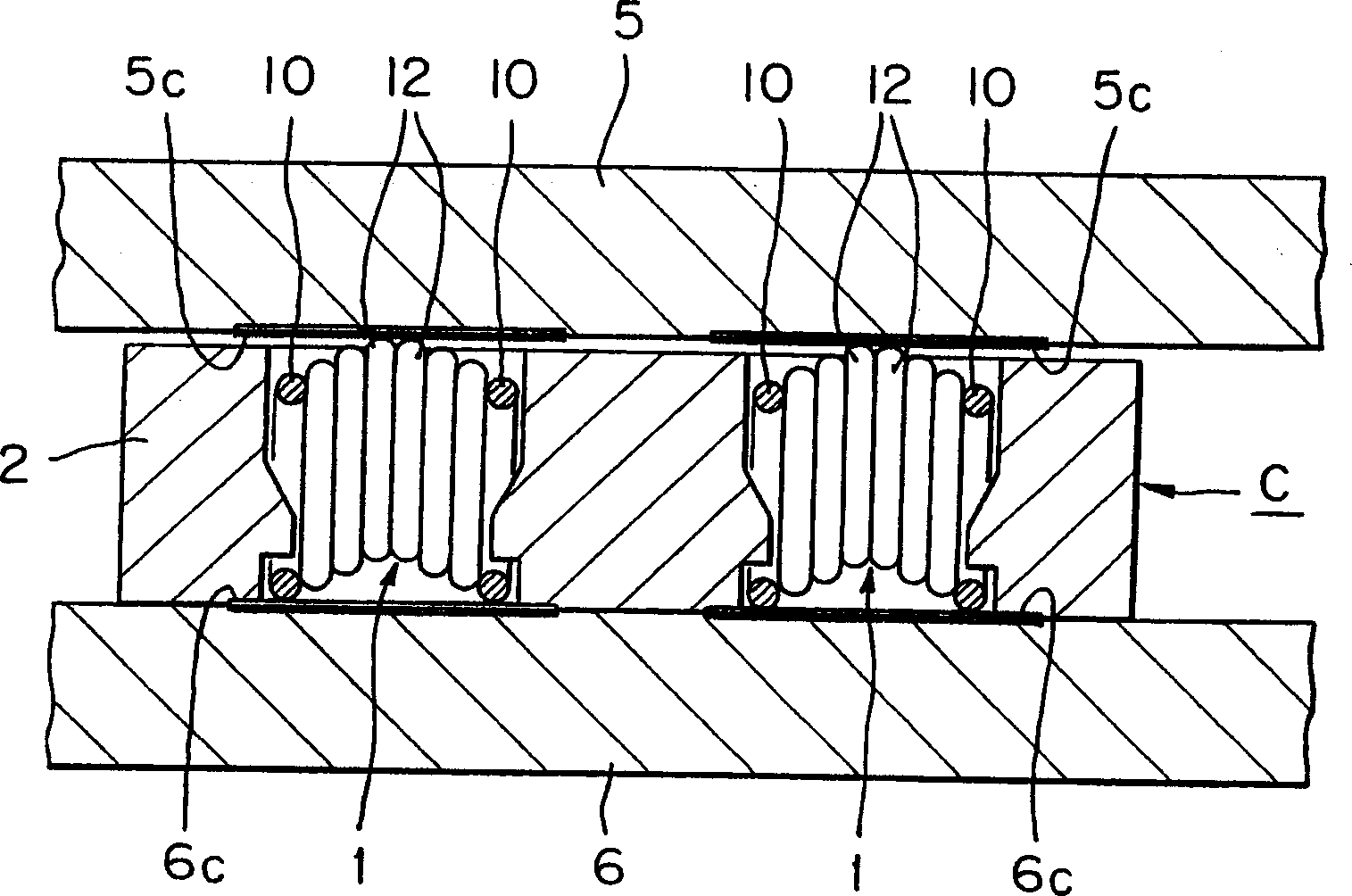
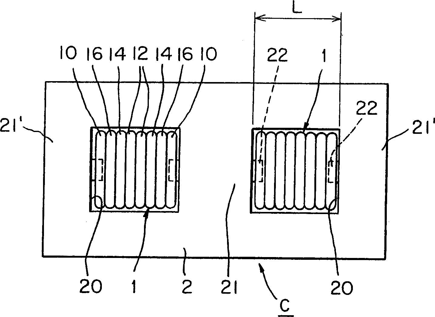
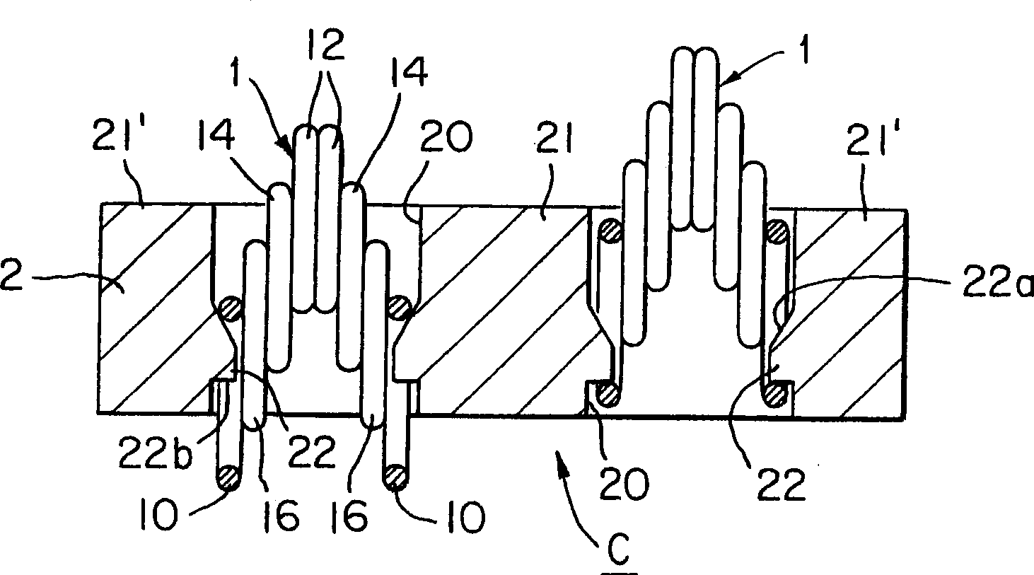
[0037] Hereinafter, embodiments of the present invention will be described with reference to the drawings. Figure 1 to Figure 11c It is a figure which shows the embodiment of the coil spring contact type connector according to this invention.

[0038] (first embodiment)

[0039] First, we pass Figure 1 to Figure 3b A first embodiment of the present invention will be described.

[0040]

[0041] exist figure 1 In the figure, as an example of the use state of the coil spring contact connector C of this embodiment, the connection state between the liquid crystal display panel 5 and the circuit board 6 in a portable terminal such as a mobile phone is shown. That is, in figure 1 Among them, the connection electrodes 5c and 6c corresponding to the liquid crystal display panel 5 and the circuit substrate 6 are electrically connected through a coil spring contact connector C.

[0042] Secondly, in Figure 2a with Figure 2b , represents a single coil spring contact connec...


PUM


Abstract

A coil spring contact connector (C) includes a plurality of coil spring contacts (1) and an insulating holder (2) holding the coil spring contacts arranged at intervals. Each coil spring contact has a pair of end contact coils (10) to be brought into contact with a terminal electrode (6c), and middle contact coils (12) radially offset relative to the end contact coils (10) so as to be brought into contact with another terminal electrode (5c). The holder is provided with openings through which contact parts of the end and the middle contact coils project outside, respectively, restrains each coil spring contact (1) from axial deformation and axial movement, and allows each coil spring contact (1) to be deformed in an offset direction thereof.

Description

technical field [0001] The present invention relates to a coil spring contact connector for connecting spring coils by being interposed between two parts and a circuit substrate for electrically connecting the connecting electrodes of the two parts. Background technique [0002] Hitherto, as a connector for electrically connecting the connection electrodes of two components and a circuit board by being interposed between them, an elastic connector composed of conductive rubber contacts contained in a case has been used. However, in such elastic connectors, there is a disadvantage that it is difficult to obtain stable contact because the conductive rubber contacts are deformed and exposed outside the case. [0003] Therefore, connectors for connecting spring coils instead of conductive rubber contacts have been proposed. This coil spring contact connector (patent 10-12777 published in 10 years of Japanese Heisei) is as Figure 12 with 13 shown. [0004] exist Figure 12 Am...

Claims


Application Information

Patent Timeline
IPC IPC(8): H01R4/48H01R12/51H01R12/71H01R13/24H05K7/10
CPCH01R12/714H01R13/2421H05K7/1069H01R12/71H01R4/48
Inventor 石塚真一远藤健司
Owner YOKOWO CO LTD
Learn More