Multi-directional air inlet extractor hood structure

A range hood, multi-directional technology, applied in the direction of oil fume removal, heating method, household heating, etc., can solve the problems of limited enhancement of smoking effect, loss of air volume of condensing oil guide plate, cost consumption, space occupation, etc., to achieve Good smoking effect, solve the problem of oil fume escape, high practical effect

Pending Publication Date: 2018-11-16
ZHONGSHAN INSE GROUP
View PDF0 Cites 2 Cited by
  • Summary
  • Abstract
  • Description
  • Claims
  • Application Information

AI Technical Summary

Problems solved by technology

[0007] 1. Increase the size of the whole machine and expand the smoke collection chamber: the product size is unconventional and not suitable for most families in China. Custom cabinets are required, which consumes cost and takes up space; the degree to which it can solve the escape of oil fume and enhance the smoking effect is limited.
[0008] 2. The volute parallel dual motor scheme: 1. There will be air intake interference between the left and right air inlets, which will cause difficulty in increasing the overall wind pressure, and cannot solve the problem of weak oil fume extraction under the public flue; 2. Under the same air volume, the noise of the double fan system is much higher than that of the single fan system;
[0009] 3. The air intake scheme around the condensing oil guide plate: 1. The condensing oil guide plate is easy to cause the loss of air volume; 2. Some areas around the condensing oil guide plate will have oil fumes escaping during frying, so the motor speed needs to be increased to Supplement the air intake flow to exhaust smoke, and the increase of motor speed will lead to increased noise, and the user's hearing experience is extremely poor

Method used


Image

  • Multi-directional air inlet extractor hood structure
  • Multi-directional air inlet extractor hood structure
  • Multi-directional air inlet extractor hood structure

Examples


Embodiment Construction

[0032] The following will clearly and completely describe the technical solutions in the embodiments of the present invention with reference to the drawings in the embodiments of the present invention.

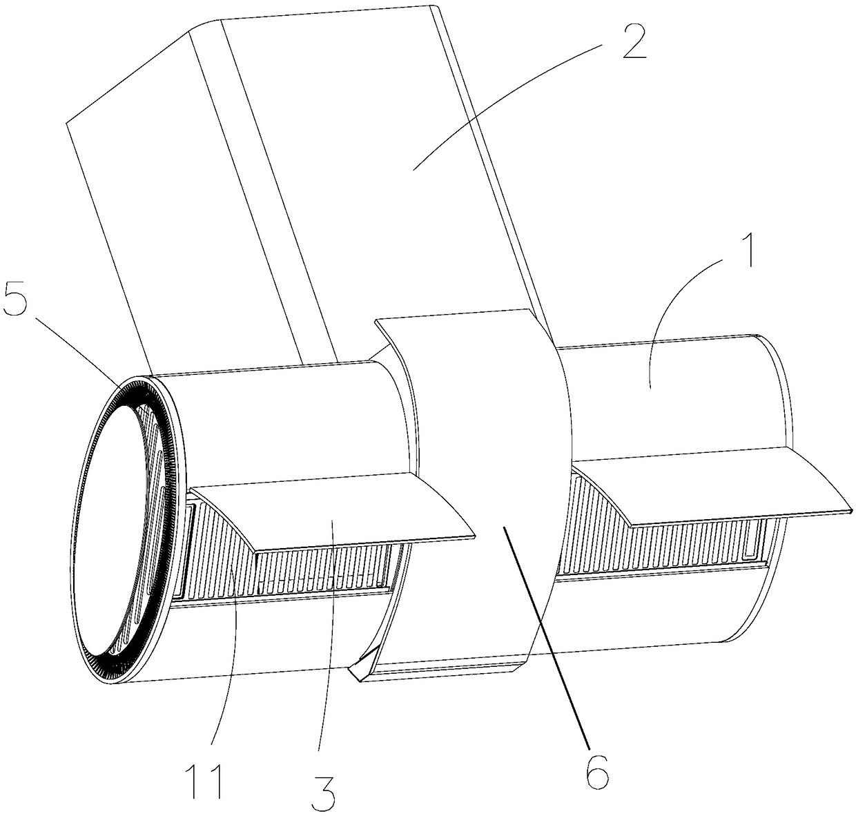
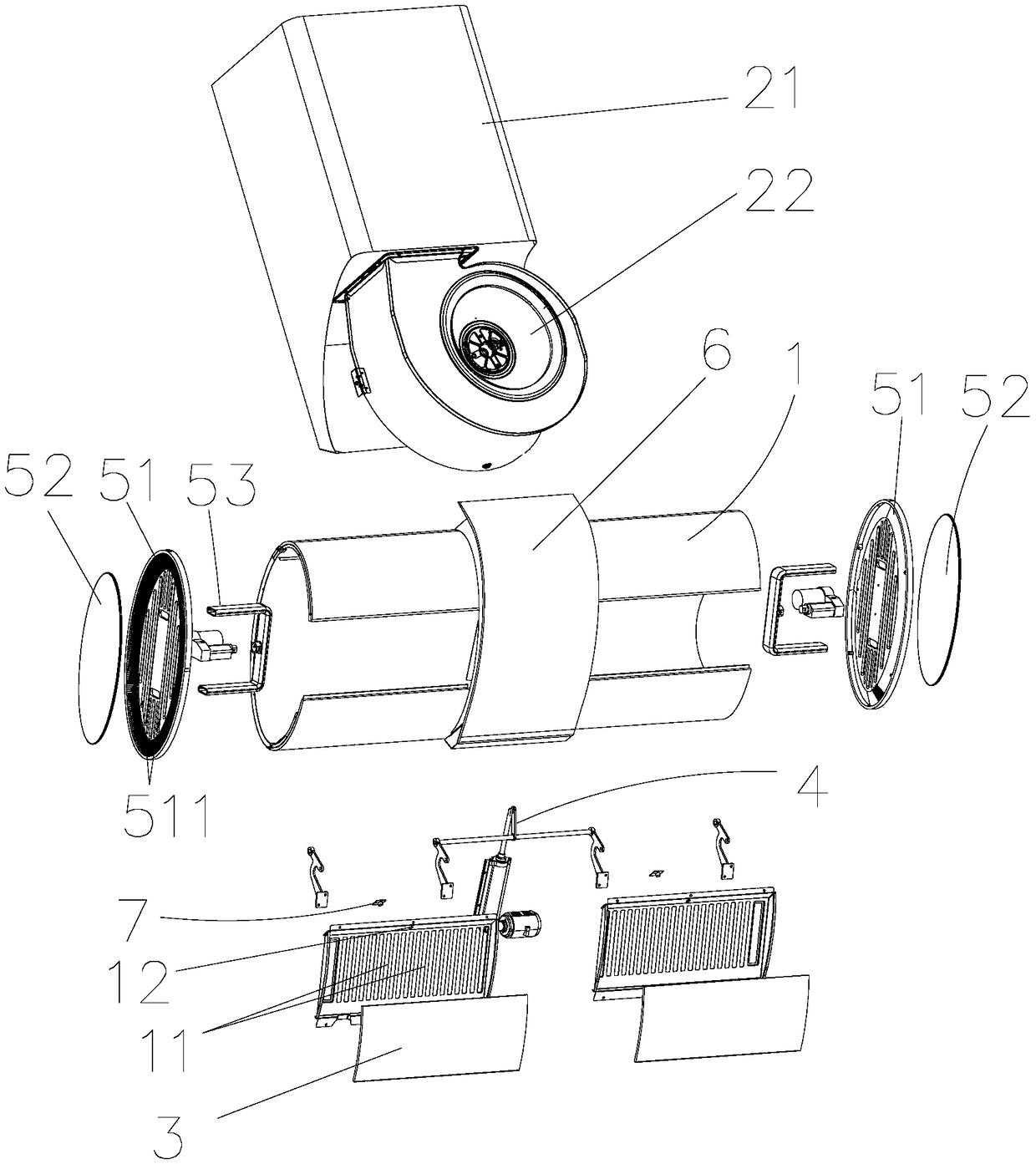
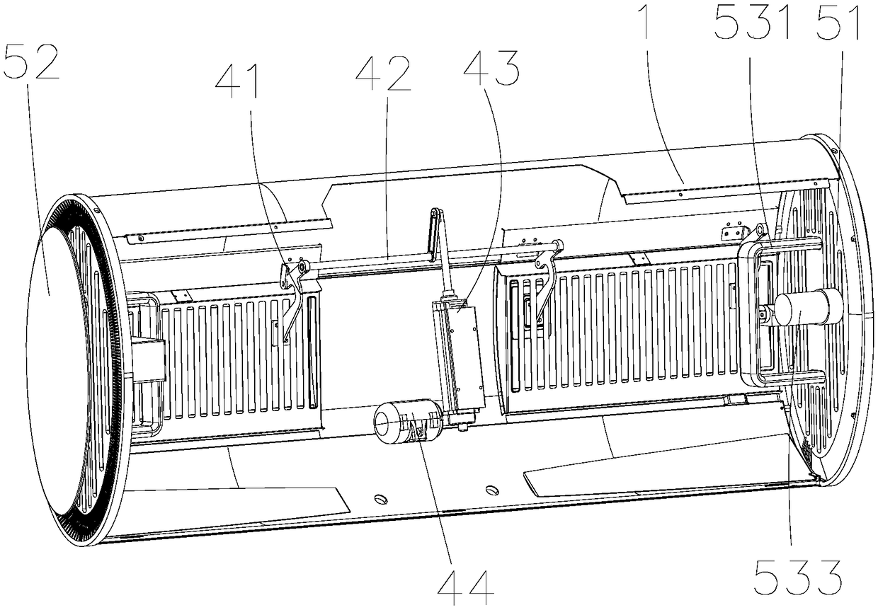
[0033] Such as Figure 1 to Figure 5 As shown, a range hood structure with multi-directional air intake includes a range hood casing 1 and a wind cabinet assembly 2 arranged above the range hood casing 1, and the range hood casing 1 is provided with Control system 6, the range hood casing 1 is provided with a main air inlet 11, and the main air inlet 11 is provided with a smoke collecting plate 3 and a swing assembly 4 that drives the smoke collecting plate 3 to open and close, and the range hood cabinet The body 1 is also provided with a side air intake assembly 5; the side air intake assembly 5 includes a side plate 51 arranged on the side of the range hood cabinet 1, and a side air intake 511 is opened on the side plate 51, and the side air intake 511 A cover plate 52 and ...


PUM


Abstract

The invention discloses a multi-directional air inlet extractor hood structure. The multi-directional air inlet extractor hood structure comprises an extractor hood box and an air cabinet assembly arranged above the extractor hood box, a control system is arranged on the extractor hood box, a main air inlet is formed in the extractor hood box, a smoke gathering plate and a swing assembly for driving the smoke gathering plate to open and close are arranged at the main air inlet, and a side air inlet assembly is arranged on the extractor hood box; and the side air inlet assembly comprises a sideplate arranged on the side face of the extractor hood box, a side air inlet is formed in the side plate, and a cover plate and a driving device for driving the cover plate to open and close are arranged at the side air inlet. By means of the multi-directional air inlet extractor hood structure, lampblack on the front face can be absorbed to the maximum degree, secondary suction and discharge arecarried out through the side air inlet assembly on the side even though a small quantity of lampblack escapes on the left and right sides, two times of lampblack suction and discharge basically solvethe problem of lampblack escaping, the appearance is attractive, and the practicability is high.

Description

【Technical field】 [0001] The invention relates to a range hood structure with multi-directional air intake. 【Background technique】 [0002] At present, the stoves used in most users’ homes are double stoves, with two burners on the left and right. It is generally difficult to clean the oily fume on both sides of the air inlet, which will cause the oily fume to escape, which will easily cause the kitchen and even the whole house to be filled with the smell of oily smoke, which will have a great impact on people's lives; [0003] In view of the above problems, the current technical solutions generally have the following options: 1. Enlarging the smoke collecting chamber. Because the smoke collecting cavity with increased left and right dimensions can form a larger smoke control area, generally the larger the left and right dimensions, the larger the smoke control area, and the better the effect of collecting and exhausting smoke. For example, the size of the range hoods curre...

Claims


Application Information

Patent Timeline
Patent Type & Authority Applications(China)
IPC IPC(8): F24C15/20
CPCF24C15/20F24C15/2021
Inventor 林天峰苏玉侠李刚凌飞林泽民
Owner ZHONGSHAN INSE GROUP
Why Eureka
Try Eureka