Liquid ammonia evaporator for denitration device line
A liquid ammonia evaporator and liquid ammonia technology, applied in the field of liquid ammonia evaporators, can solve the problems of low denitrification efficiency and achieve the effects of improving heat exchange efficiency, improving mixing adequacy, and increasing heat exchange area
- Summary
- Abstract
- Description
- Claims
- Application Information
AI Technical Summary
Problems solved by technology
Method used
Image
Examples
Embodiment 1
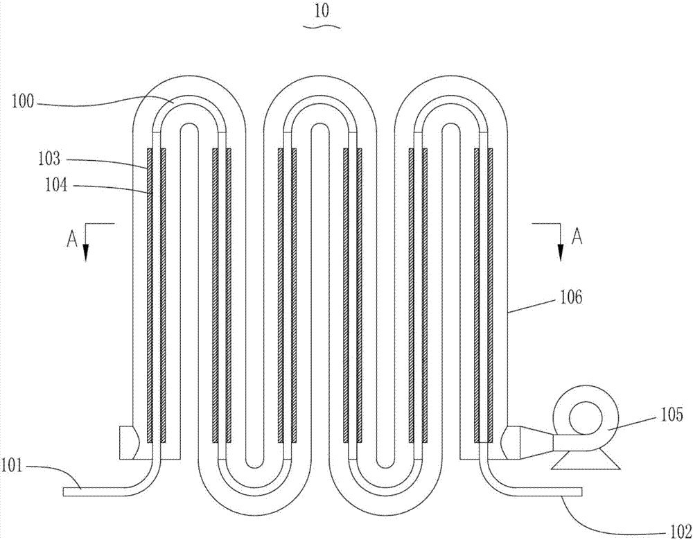
[0138] Example 1, such as figure 1 and 2 Shown:
[0139] A liquid ammonia evaporator 10 for a denitrification equipment line, comprising a liquid ammonia delivery pipe 100, one end of the liquid ammonia delivery pipe 100 is a liquid ammonia inlet port 101 connected to a liquid ammonia source, and the other end is an ammonia gas outlet port 102 A plurality of cooling fins 103 are arranged outside the liquid ammonia delivery pipe 100 .
[0140] In the liquid ammonia evaporator 10 of the present application, the heat exchange area between the liquid ammonia delivery pipe 100 and the external space is increased by arranging cooling fins 103 outside the liquid ammonia delivery pipe 100, so that the liquid ammonia can be transported more completely. The gasification of ammonia gas is formed, that is, the gasification rate of liquid ammonia is improved, so that the mixing adequacy of ammonia gas and flue gas is improved, on the one hand, the denitration efficiency is improved, and ...
Embodiment 2
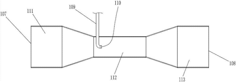
[0156] Example 2, such as image 3 as shown,
[0157] A conditioning tube for denitrification equipment line, comprising a conditioning cylinder, one end of the conditioning cylinder is a conditioning inlet 107, the other end is a conditioning outlet 108, the conditioning tube also includes an ammonia gas inlet Pipe 109, one end of the ammonia gas inlet pipe 109 extends into the tempering cylinder, and the other end is located outside the tempering cylinder.
[0158] The quenching and tempering tube of the present application, when in use, blows air at the quenching and tempering inlet 107 or other chemical reactions in the middle of the denitrification process to dilute the high-concentration ammonia gas and make it into lower-concentration ammonia Gas, on the one hand, directly makes the liquid ammonia fully gasified, on the other hand, it is also more conducive to the uniform mixing of ammonia gas and flue gas, so that the denitrification efficiency can be improved and the...
Embodiment 3
[0171] Example 3, such as Figure 4 and 5 Shown:
[0172] An ammonia injection grid used for a denitrification equipment line, comprising an ammonia injection main pipe 114, one end of the ammonia injection main pipe 114 communicates with the quenching and tempering outlet 108 of the quenching and tempering tube, and the other end is located at the inlet pipe of the denitration tower 117. In the flue gas pipeline 115 , the part of the ammonia injection main pipe 114 located in the flue gas pipeline 115 is an ammonia injection section, and several second nozzles 118 are arranged on the ammonia injection section.
[0173] The ammonia injection grid of the present application sprays the low-concentration ammonia gas mixed with air into the flue gas pipe 115 through the second nozzle 118, so that the flue gas and ammonia gas are fully mixed before entering the denitrification tower 117, ensuring In the denitration tower 117, the nitrogen oxides in the flue gas can more fully con...
PUM
 Abstract
Description
Claims
Application Information
 - R&D
- Intellectual Property
- Life Sciences
- Materials
- Tech Scout
- Unparalleled Data Quality
- Higher Quality Content
- 60% Fewer Hallucinations
Browse by: Latest US Patents, China's latest patents, Technical Efficacy Thesaurus, Application Domain, Technology Topic, Popular Technical Reports.
© 2025 PatSnap. All rights reserved.Legal|Privacy policy|Modern Slavery Act Transparency Statement|Sitemap|About US| Contact US: help@patsnap.com


