Supercharge Your Innovation With Domain-Expert AI Agents!

Dust collector box of vacuum cleaner

A technology for vacuum cleaners and dust collection boxes, applied in vacuum cleaners, suction filters, applications, etc., can solve the problems of suction loss, influence, and increase the number of parts, and achieve the effects of supporting suction loss, simplifying the internal structure, and improving suction efficiency

Inactive Publication Date: 2003-07-02
LG ELECTRONICS (TIANJIN) APPLIANCES CO LTD
View PDF0 Cites 4 Cited by
  • Summary
  • Abstract
  • Description
  • Claims
  • Application Information

AI Technical Summary

Problems solved by technology

This structure not only increases the number of parts and complicates the assembly process, but also the connecting pipe will inevitably cause suction loss, which will eventually lead to a reduction in the suction efficiency of the vacuum cleaner and have a negative impact on the performance of the vacuum cleaner

Method used


Image

  • Dust collector box of vacuum cleaner
  • Dust collector box of vacuum cleaner
  • Dust collector box of vacuum cleaner

Examples


Embodiment Construction

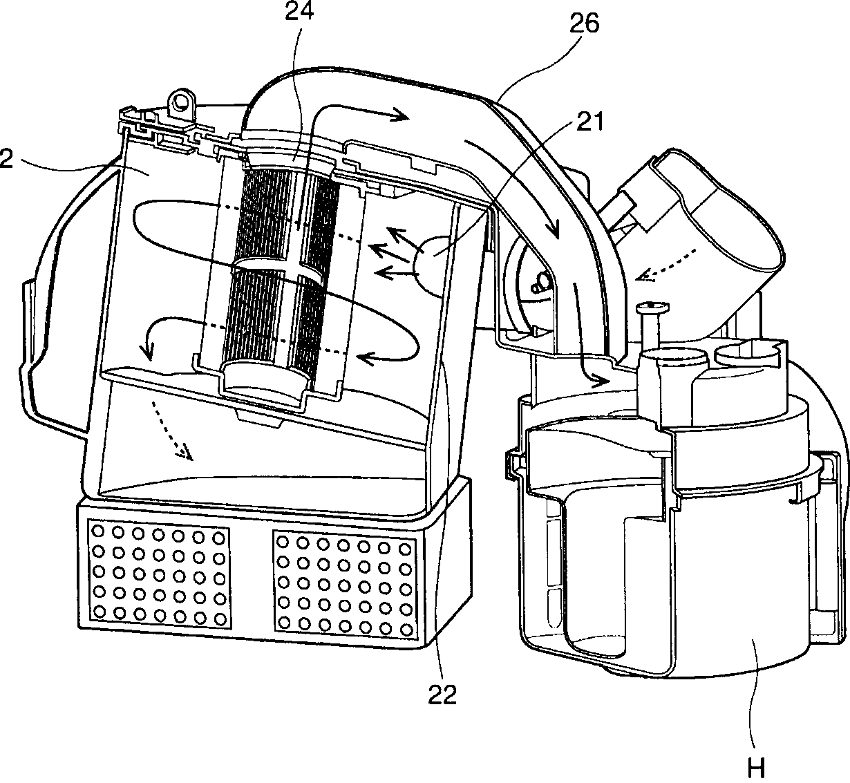
[0016] Such as Figure 4 , Figure 6 As shown, the dust collection box 100 for a vacuum cleaner of the present invention is mainly composed of a box body 130 and a box cover 110 that opens and closes the box body 130. The box 130 is a cylindrical shape with an open upper end, and an air inlet 134 is provided on the upper part. The direction of the air inlet 134 is consistent with the tangential direction of the inner surface of the box 130. The air sucked in through the inlet 134 will form a vortex in the box 130. The box cover 110 is installed on the upper mouth of the box body 130 and used for opening and closing the box body 130. A detachable filter 114 is installed in the center of the lower part, and a handle 116 for grasping is provided on the box cover 110 to facilitate the separation of the dust box 100 from the main body of the vacuum cleaner. The handle can also be provided on the side of the box 130. The filter 114 has a hollow cylindrical shape and is used to filter fin...


PUM


Abstract

A dust collecting box of vacuum cleaner is composed of a cylindrical box body with open top and air inlet, a cover installed on the top of the box body, a filter under the cover, and a lower exhaust pipe connected to lower end of the filter. Its advantages are the shortest air channel and high sucking efficiency.

Description

1. Technical Field [0001] The invention relates to a dust collecting box for a vacuum cleaner, in particular to a circulating dust collecting box capable of shortening the air flow path in the main body of the vacuum cleaner. 2. Background technology [0002] The vacuum cleaner uses the suction force generated by its main body to suck air containing foreign matter such as dust into the main body, filter out the foreign matter inside the main body, and then exhaust the clean air to the outside of the main body. For this reason, a motor that can generate suction and a filter device for filtering the air are installed inside the main body of the vacuum cleaner. Traditional filter devices mostly use paper dust bags, which only allow air to pass through, and collect dust and other foreign objects in the dust bag. After this kind of dust bag is filled with foreign matter such as dust, it will be disposed of along with the foreign matter, thus causing a waste of materials; moreover, as ...

Claims


Application Information

Patent Timeline
Patent Type & Authority Applications(China)
IPC IPC(8): A47L9/00A47L9/10A47L9/16
Inventor 梁炳善
Owner LG ELECTRONICS (TIANJIN) APPLIANCES CO LTD
Features
  • R&D
  • Intellectual Property
  • Life Sciences
  • Materials
  • Tech Scout
  • Unparalleled Data Quality
  • Higher Quality Content
  • 60% Fewer Hallucinations
Learn More