

Spinning device
A fiber and hollow technology, which is applied in the field of spinning devices, can solve the problems of poor spinning performance, insufficient spinning strength, and high fiber loss.
- Summary
- Abstract
- Description
- Claims
- Application Information
AI Technical Summary
Problems solved by technology
Method used
Image

Examples
Embodiment Construction
[0022] An example of the present invention will be described below, but it is not limited to this example unless the gist of the present invention is exceeded.
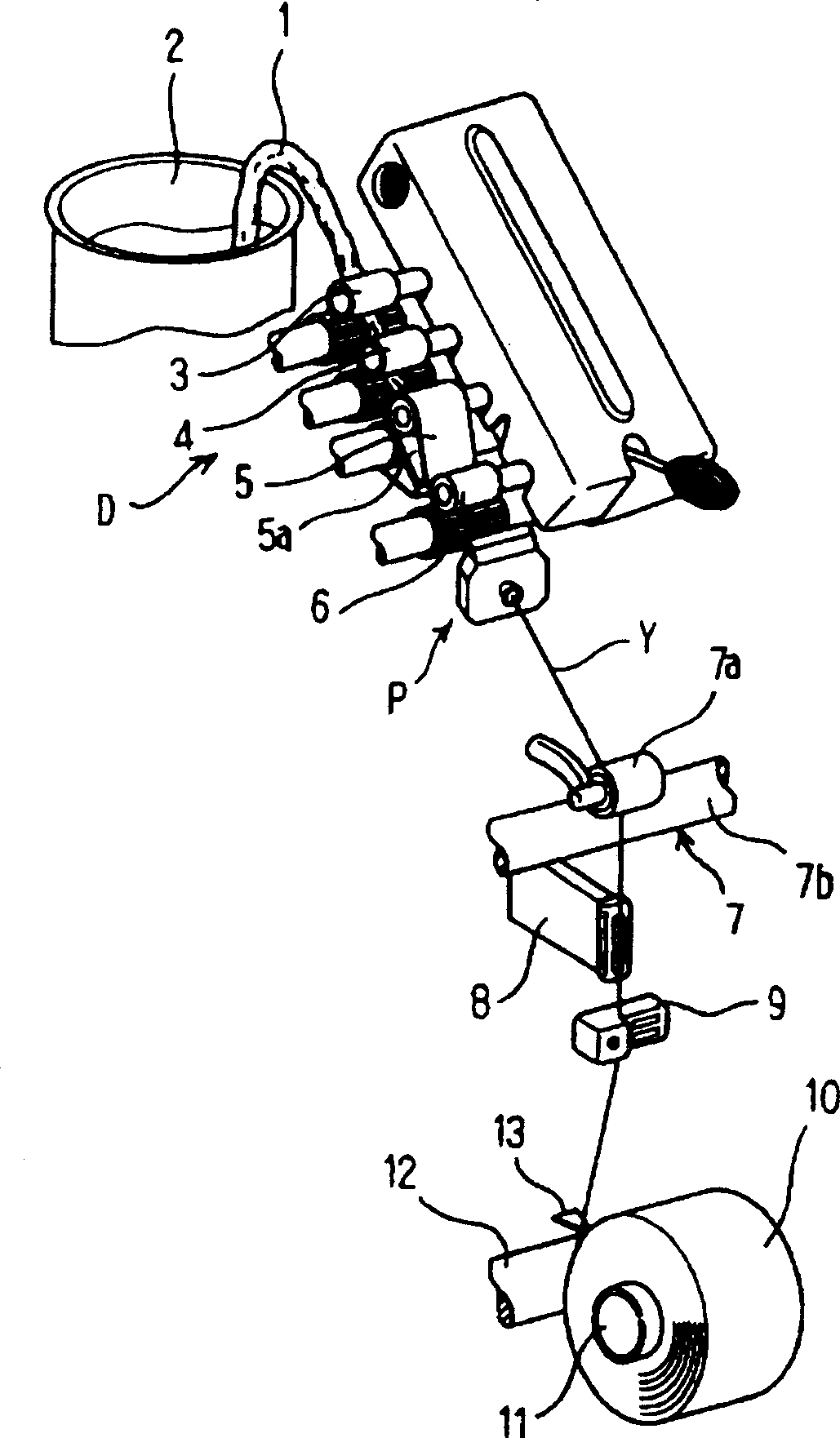
[0023] First, use figure 1 The overall configuration of a spinning device as an example will be described.
[0024] 1 is the fiber bundle before being stretched in the can 2, and D is a 4-line stretching device as an example. The second roller 5 and the front roller 6 are composed. P is a spinning section described later, 7 is a yarn feeding member composed of a nip roller 7a and a delivery roller 7b, and 8 is a device for temporarily storing the yarn discharged from the spinning section P that restarts spinning during the piecing operation. Slack bobbin, 9 is a yarn cleaner. 10 is a package formed on a bobbin 11 supported by a bobbin holder not shown in the figure, and the package 10 is configured such that its surface abuts against a rubbing roller 12 to rotate. 13 is the oscillating yarn guide of the oscillatin...
PUM
 Abstract
Description
Claims
Application Information