Device for guiding metal strip on gas cushion

A technology of metal strips and strips, applied in the direction of winding strips, transportation and packaging, loading/unloading, etc., can solve problems such as uneven distribution

Inactive Publication Date: 2003-07-02
彼得・埃布纳
View PDF2 Cites 5 Cited by
  • Summary
  • Abstract
  • Description
  • Claims
  • Application Information

AI Technical Summary

Problems solved by technology

However, a disadvantage of the nozzle area that tapers towards the longitudinal edge of the metal strip is that only a uniform heat treatment of the...

Method used


Image

  • Device for guiding metal strip on gas cushion
  • Device for guiding metal strip on gas cushion
  • Device for guiding metal strip on gas cushion

Examples


Embodiment Construction

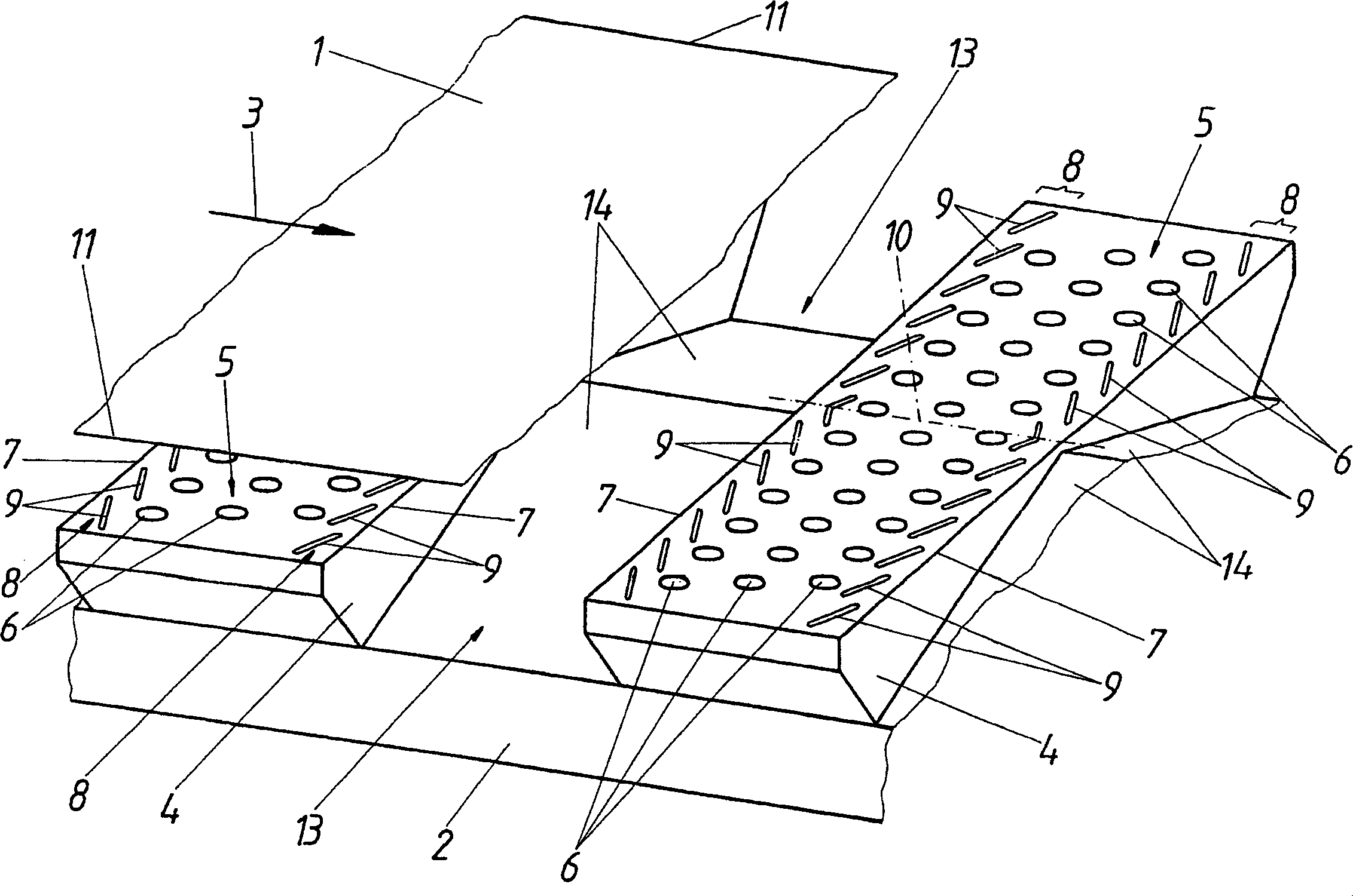
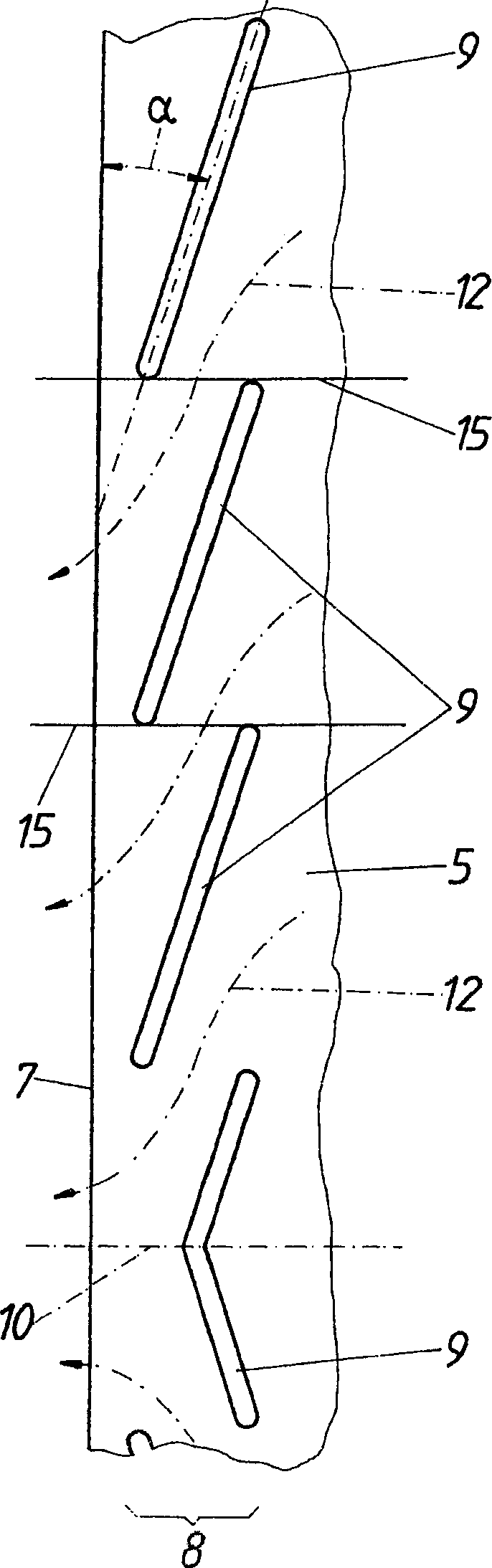
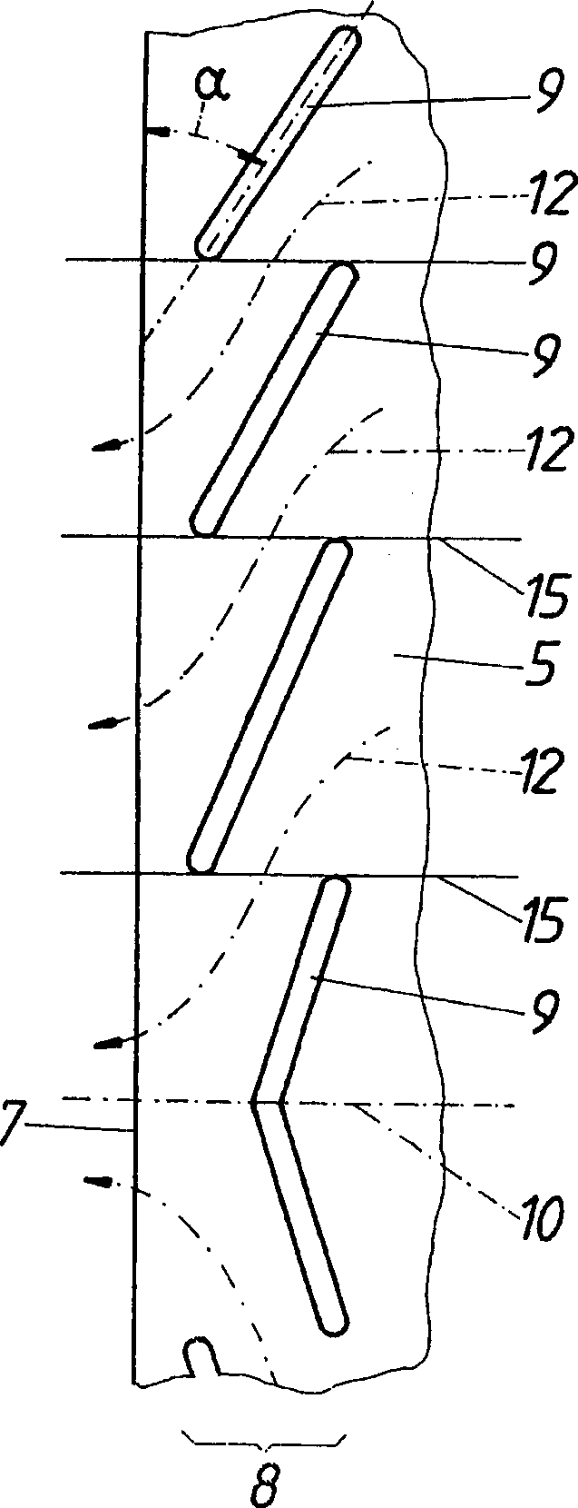
[0012] according to figure 1 , the device for guiding the metal strip 1 comprises a frame 2 which carries blowing boxes 4 which are positioned successively in the longitudinal direction 3 of the strip and form a nozzle area 5 . Said nozzle area extends transversely to the strip longitudinal direction 3 and is provided with hole-shaped nozzles 6 distributed over the surface area of ​​the nozzle area through which gas, such as air, is blown towards the metal strip to form an air cushion. Along the edge 7 of the nozzle region 5 running transversely to the longitudinal direction 3 of the strip are arranged slot-shaped nozzles 8 which consist of nozzle slots 9 . Said nozzle slots 9 arranged in a row parallel to the edge are inclined inwardly relative to the edge 7 (starting from the center of the respective edge 10 ), so that the nozzle slots 9 opposite each other with respect to the nozzle area 5 make the nozzle area 5 narrows relative to the longitudinal edge 11 of the metal str...


PUM


Abstract

A device for guiding a metal strip (1) on a gas cushion with blast boxes (4), arranged in a row at a separation from each other, in the longitudinal direction (3) of the strip. The nozzle fields (5) of the above, which extend across the longitudinal strip direction (3), comprise hole jets (6) arranged over the field surface and slit jets (8) arranged along the edges (7) running transverse to the longitudinal strip direction (3). According to the invention, in order to achieve advantageous construction conditions, the slit jets (8) along the edges (7) comprise several jet slits (9) arranged in a series of rows, one behind the other, parallel to the edge, which, starting from the mid-point (10) of an edge, are directed inwards, relative to the edge (7).

Description

technical field [0001] The invention relates to a device for guiding a metal strip on an air cushion, with a blower box, which is arranged successively in the longitudinal direction of the strip, and whose nozzle area, which extends transversely to the longitudinal direction of the strip, comprises a nozzle area distributed on the surface of the area Orifice-shaped nozzles in the area and slot-shaped nozzles along the edges extending transversely to the longitudinal direction of the strip. Background technique [0002] In order to be able to convey a metal strip floating on an air cushion in the longitudinal direction of the strip, it is known (DE3026132A) to provide blowing boxes, which are arranged one after the other in the longitudinal direction of the strip and whose nozzle areas extend transversely to the longitudinal direction of the strip and include distribution Orifice nozzles on the area surface area. The gas flowing through said hole-shaped nozzles against the m...

Claims


Application Information

Patent Timeline
IPC IPC(8): B65G51/03B65H29/52F26B13/20
CPCF26B13/104B65H29/52B65G51/03B65H2701/173B65G69/20
Inventor 彼得·埃布纳
Owner 彼得・埃布纳
Why Eureka
Try Eureka