Stirring heat transfer device

A stirring plate, hollow shaft technology, applied in indirect heat exchangers, heat exchanger types, lighting and heating equipment, etc., can solve problems such as wear, water leakage, cracks or openings at the bottom of the shell, and achieve the effect of prolonging life.

Inactive Publication Date: 2003-08-13
TSUKISHIMA KIKAI CO LTD
View PDF0 Cites 15 Cited by
  • Summary
  • Abstract
  • Description
  • Claims
  • Application Information

AI Technical Summary

Problems solved by technology

According to the prior art, the material to be processed supplied from the feed inlet of the stirring heat transfer device is transferred into the device while being heated or cooled while stirring, and then the processed finished product or dry product is taken out from the discharge port. All the stirring plates are formed by inclination relative to the plane that is at right angles to the axial axis of the rotating shaft, so the finished product or dried product will strongly press the bottom of the housing of the stirring heat transfer device, and the processed dried product At the same time, it is difficult to discharge from the discharge port. At the same time, by repeatedly performing the strong pressing action of the dried product, etc., it will cause the bottom of the shell to wear and cause damage such as cracks or openings, and also induce heat exchange into the shell. Leakage of media such as steam, warm or cold water

Method used


Image

  • Stirring heat transfer device
  • Stirring heat transfer device
  • Stirring heat transfer device

Examples


Embodiment 1

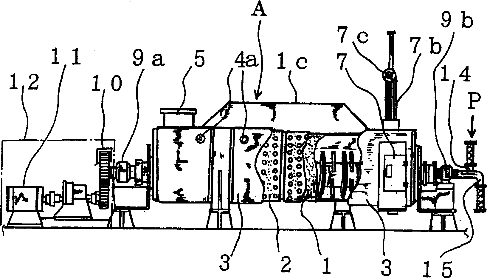
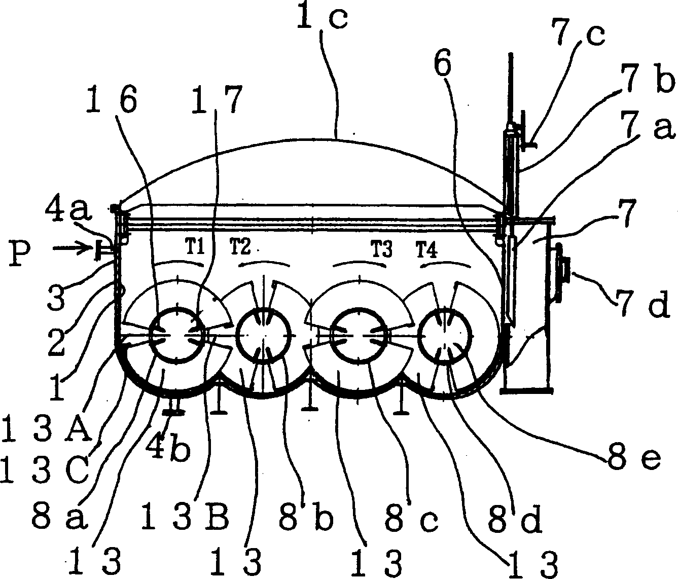
[0022] Figure 1 ~ Figure 4 It is a figure which shows Example 1 of the stirring heat transfer apparatus of this invention, and this is demonstrated.

[0023] In this embodiment, A is a stirring heat transfer device, which is provided with an upper cover 1c and a casing 1. On the outer periphery of the casing 1, for example, water jackets 2 such as indented flat water jackets are provided in multiple axial directions. The outer periphery of the water jacket 2 constitutes an outer casing 3, and the outer casing 3 is provided with the heat exchange medium inlet 4a to the side of the water jacket, so that as figure 1 and image 3 The shown heat exchange medium P is flowable. And the heat exchange medium P is discharged from the heat exchange medium outlet 4b on the side of the water jacket. Additionally, if image 3 As shown, the bottoms of the casing 1, the water jacket 2, and the outer casing 3 are waved so as to surround four stirring plates 13 described later. The housin...

Embodiment 2

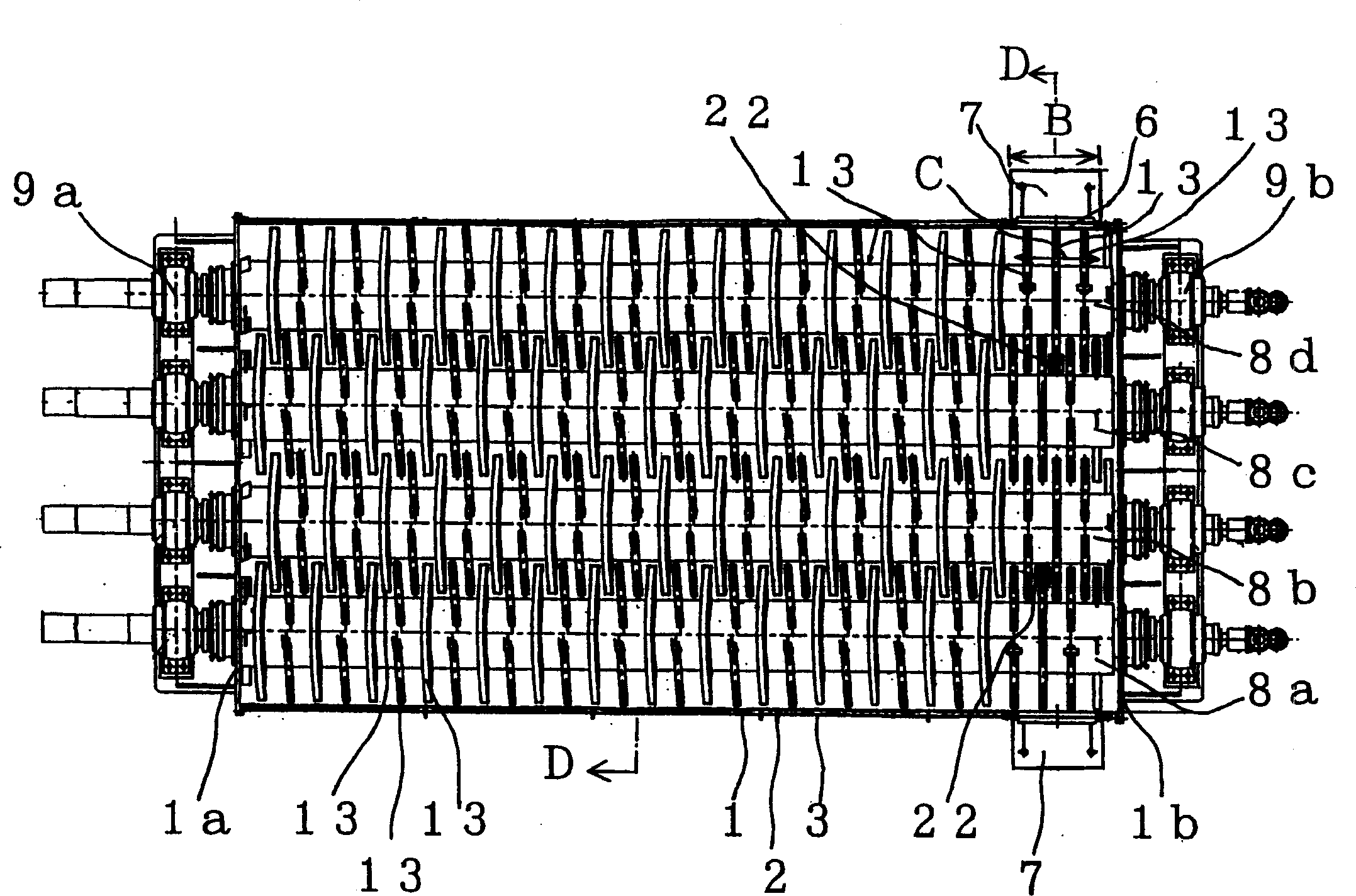
[0041] Embodiment 2 of the stirring heat transfer device of the present invention exemplifies a technology in which relatively large rake blades are provided at the front end of the stirring plate arranged substantially perpendicular to the axis of the hollow shaft shown in Embodiment 1.

[0042] The larger rake blade 22, in figure 2 The middle represents on the hollow shaft 8a, 8d, in Figure 4 (a) means it is on 8b. The larger rake blades 22 have a certain width in the horizontal or vertical direction as described later, and are characterized by increasing the rake area of ​​the processed material or dry matter, etc., and are arranged on the row. The hollow shafts 8a to 8d near the feed port 7 are arranged in the axial direction of the bearing portions of the hollow shafts 8a to 8d, that is, on the hollow stirring plate 13 arranged in a direction substantially perpendicular to the length of the hollow shafts, thereby exerting its effect. That is, after stirring, heat-tran...


PUM


Abstract

The invention relates to a stirring heat transfer device, which prevents the abrasion of a bottom part of a casing by preventing treated matter or a dried product from being pressed to the bottom part at the other end (rear end) of the casing. Four approximately cylindrical hollow shafts are arranged in parallel in the casing rotatably along the longitudinal direction of the casing. Both ends of the hollow shafts are respectively projected from one end face 1a and the other end face of the casing in a sealed condition, and rotatably supported by bearing parts. The desired number of discharge ports are formed on the casing, or a part near a lower part and a side part of a jacket or a case body at the other end (rear end) of the hollow shafts, and a plurality of hollow stirring plates are mounted approximately vertically to a longitudinal axis of the hollow shafts without being inclined, on the hollow shafts near the discharge ports.

Description

technical field [0001] The invention relates to a plurality of rotatable hollow shafts arranged in parallel in a casing, and a plurality of hollow stirring plates are obliquely arranged in each hollow shaft, and then through the A hollow stirring plate and a rake blade larger than the hollow stirring plate are arranged in a substantially vertical direction in the hollow shaft portion of the width, so that heat exchange treatment can be performed while stirring the material to be treated supplied into the housing. Stirring device for smooth discharge. Background technique [0002] In the past, as this kind of agitation heat transfer device, for example, a plurality of rotating shafts are spaced in parallel in a substantially horizontal housing with a water jacket structure on the outer periphery, and stirring plates are provided on the rotating shafts. The rotating shaft and the stirring plate are hollow, and a heat exchange medium is passed through the inside of the rotatin...

Claims


Application Information

Patent Timeline
Patent Type & Authority Applications(China)
IPC IPC(8): F26B25/04F26B3/24F26B17/20F28D11/02
CPCF26B3/20F26B15/26F26B25/04
Inventor 佐藤澄人吉田明弘
Owner TSUKISHIMA KIKAI CO LTD
Why Eureka
Try Eureka