Blowing machine motor

A blower and motor technology, applied in the installation of motor fan components, electromechanical devices, mechanical equipment, etc., can solve problems such as obstruction, low blower operating efficiency, and loud noise

Inactive Publication Date: 2003-08-20
JOHNSON ELECTRIC SA
View PDF0 Cites 104 Cited by
  • Summary
  • Abstract
  • Description
  • Claims
  • Application Information

AI Technical Summary

Problems solved by technology

This causes obstructions in the air flow path and creates a lot of noise, as well as making the blower operate inefficiently

Method used


Image

  • Blowing machine motor
  • Blowing machine motor
  • Blowing machine motor

Examples


Embodiment Construction

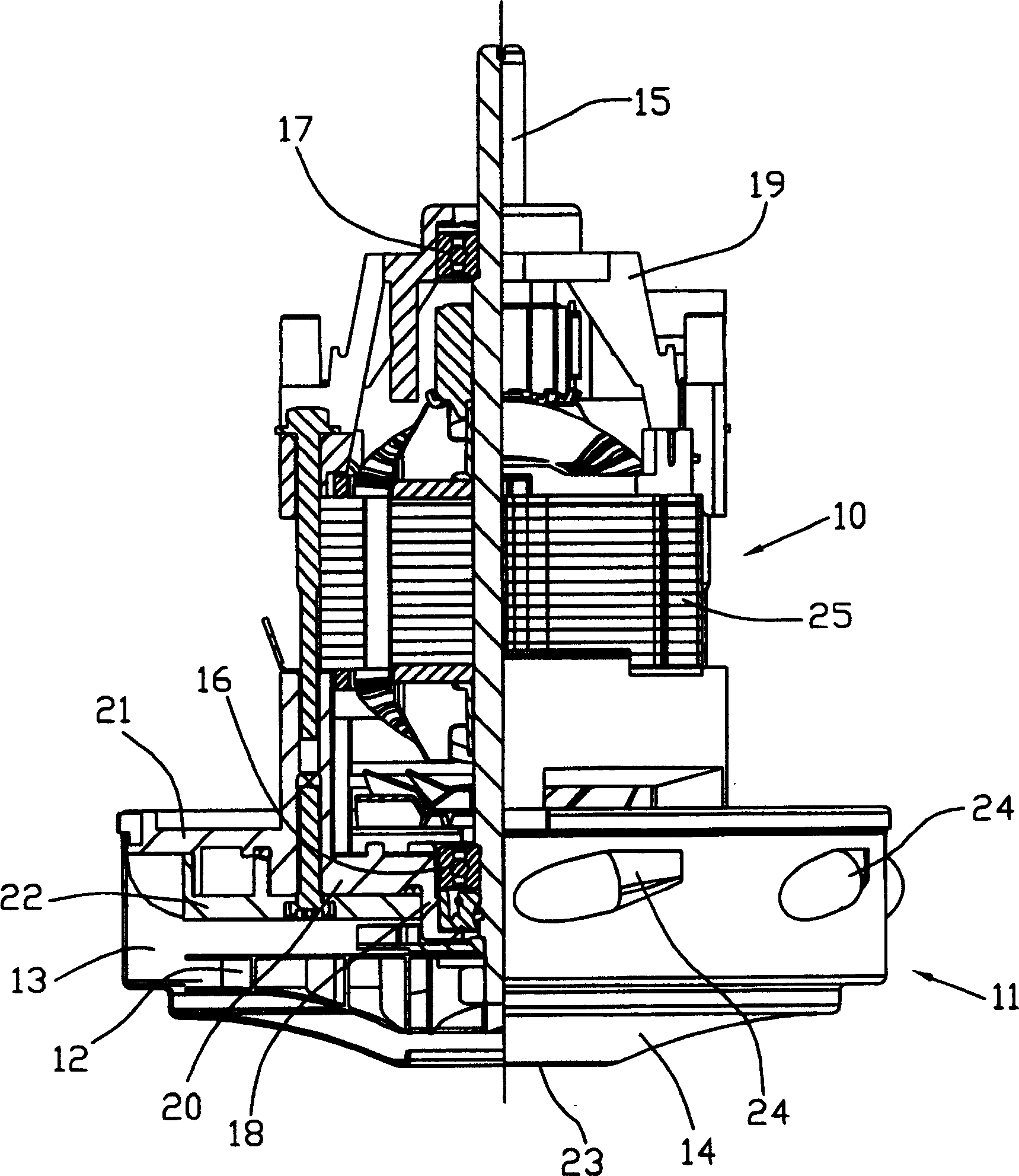
[0013] figure 1 A partial cutaway view showing the bypass duct blower motor assembly. The assembly has a motor section 10 and a blower section 11 . The motor section includes a general purpose motor. The operation of this motor is well known and will not be described.

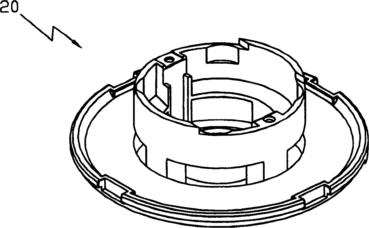
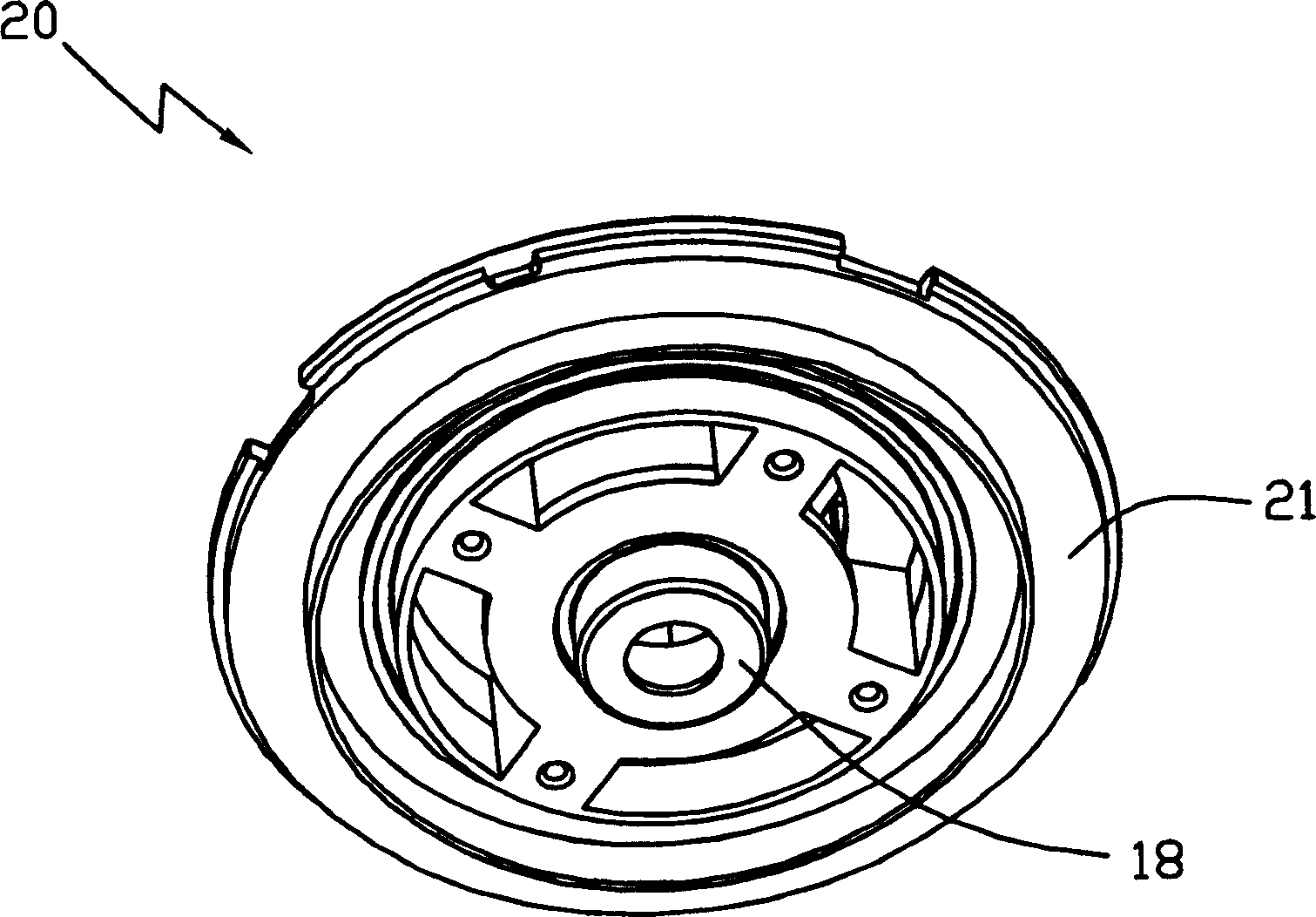
[0014] The blower section 11 includes a centrifugal fan-type impeller 12 located in an impeller chamber 13 defined by an elongated cup-shaped impeller case 14 having a bottom wall and a peripheral wall, and two Or combined with a flange 21 of a fan end bracket 20 of the motor. The fan end bracket 20 separates the blower section 11 from the motor section 10 and closes the open end of the impeller case 14 . The impeller box 14 has a single central inlet 23 in its bottom wall and a plurality of outlets 24 in its peripheral wall.

[0015] The universal motor has a shaft 15 mounted on bearings 16 and 17 . The bearing 17 is installed on a boss 18 in the fan end bracket 20 , and the bearing 17 is installed on an...


PUM


Abstract

A diffuser plate 22 for a bypass blower motor assembly has a number of vanes 34 for guiding air flow from an impeller to outlet openings in an impeller housing. Each vane has two curved air guiding blades 36, 37. One blade 36 guides the air axially and circumferentially from the impeller towards the outlet openings and the other blade 37 guides the air radially through the outlet openings.

Description

technical field [0001] The present invention relates to a blower motor, and more particularly to a blower motor for a bypass or wet vacuum cleaner. Background technique [0002] The blower motor of a bypass vacuum cleaner has an impeller for driving air from the inlet to the outlet of an impeller housing mounted on the motor without passing it through the motor itself. This structure allows the vacuum cleaner to pick up dust and dirt while also picking up liquids without damaging the electric motor. [0003] The impeller is mounted on a shaft of the motor. The shaft is supported on a bearing that passes through an end bracket of the motor case, which also serves as a spacer between the motor and the impeller. A diffuser disk is disposed at the end of the bracket, and air is directed through the impeller to the outlet within the impeller chamber. Typically, the diffuser directs the air circumferentially and / or axially against the air pressure developed in the impeller cavi...

Claims


Application Information

Patent Timeline
Patent Type & Authority Applications(China)
IPC IPC(8): A47L9/00A47L5/22A47L7/00A47L9/22F04D29/44
CPCA47L5/22
Inventor 谭少振潘广业
Owner JOHNSON ELECTRIC SA
Why Eureka
Try Eureka