Thermal sensitive printers

A technology of thermal printers and thermal heads, which is applied in printing devices, printing, etc., and can solve problems such as troublesome assembly work and high skills

Inactive Publication Date: 2003-09-03
SEIKO INSTR INC
View PDF0 Cites 11 Cited by
  • Summary
  • Abstract
  • Description
  • Claims
  • Application Information

AI Technical Summary

Problems solved by technology

Therefore, the conventional thermal printer has a disadvanta

Method used


Image

  • Thermal sensitive printers
  • Thermal sensitive printers
  • Thermal sensitive printers

Examples


Embodiment Construction

[0032] The foregoing embodiments of the present invention will now be described in detail with reference to the accompanying drawings.

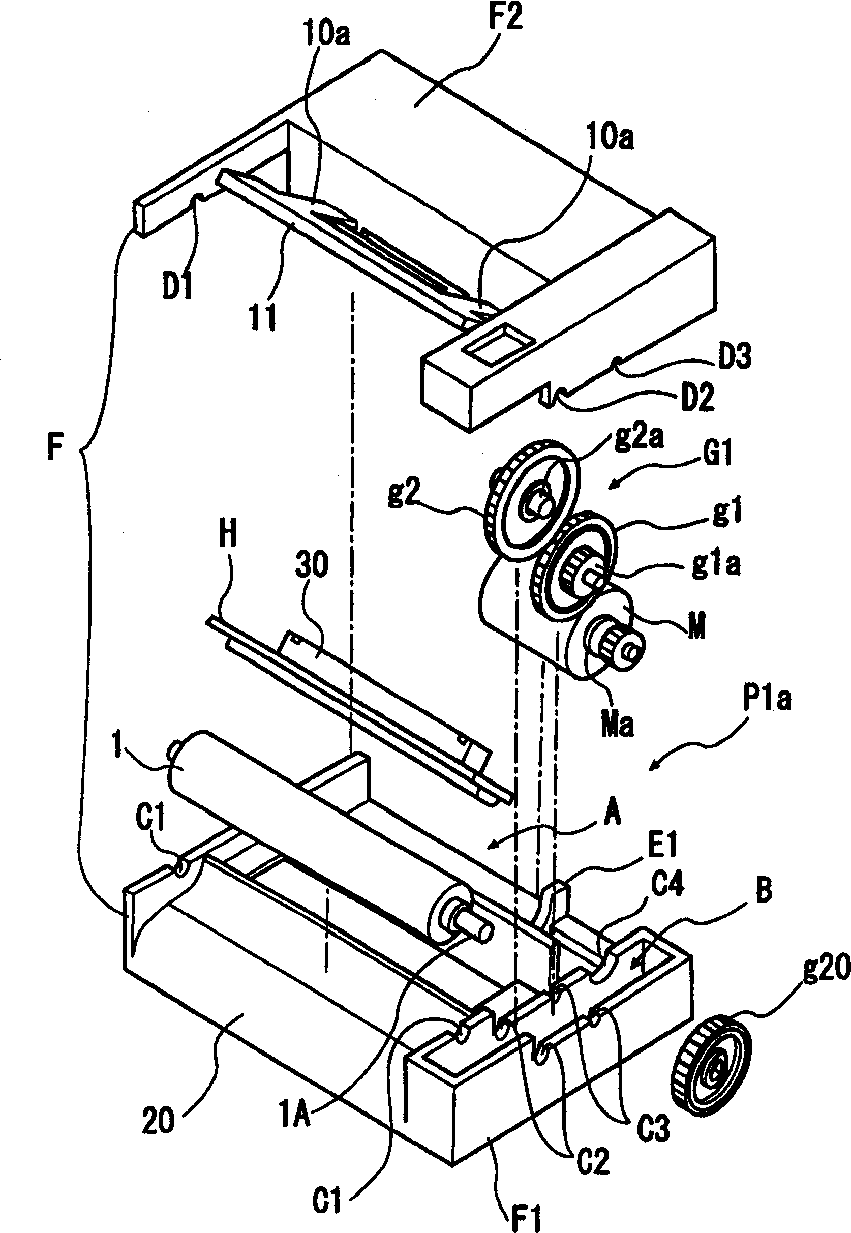
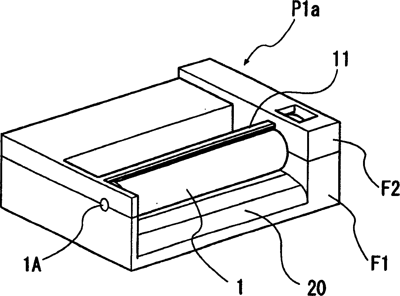
[0033] figure 1 Shown is an exploded perspective view of the thermal printer according to the first embodiment of the present invention. figure 2 Shown is a perspective view of the assembled thermal printer.

[0034] Such as figure 1 A thermal printer P1a according to the first embodiment is shown, equipped with a frame F composed of a lower frame F1 and an upper frame F2, the frame F having a pair of side wall portions disposed opposite to each other in the paper width direction at a predetermined interval .

[0035] The frame F is formed from an injection molded article of, for example, plastic such as polycarbonate.

[0036] The upper surface of the lower frame F1 and the lower surface of the upper frame F2 are manufactured as a coupling structure (that is, the end faces in the structure conform to each other, and after coupling, ther...


PUM


Abstract

To provide a thermal printer that is capable of simplifying the assembling work to reduce the manufacturing cost. A frame (F) is comprised of a lower frame member (F1) and an upper frame member (F2) that is dividable up and down, and receiving portions (receiving portion A, gear receiving portion B) for receiving a line thermal head (H), a platen roller (1), a motor (M), and a gear (G1) are formed in the lower frame member, respectively, and at the same time, a plurality of holder portions (C1 to C4, D1 to D4) for rotatably clamping each rotary shaft of the platen roller and the motor when both frames are coupled together are formed in side wall portions of the lower frame member and side wall portions of the upper frame member.

Description

technical field [0001] The present invention relates to a kind of miniature thermal printer installed on various portable information devices or other similar devices, in particular to a printer having a pressure device with a simplified structure for extruding a linear thermal head to make a linear The thermal head can be pressed onto the surface of a platen roller. Background technique [0002] A general conventional line-dot type thermal printer consists of a linear thermal head and a platen roller installed in a frame opposite to each other, a driving device, a conveying mechanism for conveying thermal recording paper, and the like. [0003] A structural example of a conventional thermal printer will be described with reference to the exploded perspective view 10 . [0004] As shown in FIG. 10, a platen roller 102, a thermal head H, two coil springs 104 for biasing the thermal head against the platen roller 102, and two coil springs 104 for rotatably supporting the plat...

Claims


Application Information

Patent Timeline
IPC IPC(8): B41J2/32B41J11/18
CPCB41J11/24B41J2/32B41J11/18
Inventor 内藤昭夫
Owner SEIKO INSTR INC
Why Eureka
Try Eureka