Sewing machines

A sewing machine and driving mechanism technology, which is applied to sewing machine components, sewing machine casings, sewing machine thread take-up devices, etc., can solve the problems of lowering the quality of sewing products, lowering work efficiency, and long residual length.

Inactive Publication Date: 2003-09-03
JUKI CORP
View PDF1 Cites 7 Cited by
  • Summary
  • Abstract
  • Description
  • Claims
  • Application Information

AI Technical Summary

Problems solved by technology

If the remaining length is long, the end of the upper thread exposed from the needle drop point at the beginning of the next sewing will be long, and the appearance of the sewn product will be deteriorated. Therefore, the operator must remove the upper thread end by hand after sewing. head cut off, its work efficiency is low
On the other hand, if the remaining length is short, the upper thread is pulled out from the threading hole of the needle when the needle is lowered at the next sewing start, and then the needle is lowered to the fabric, and the needle remai

Method used


Image

  • Sewing machines
  • Sewing machines
  • Sewing machines

Examples


Embodiment Construction

[0032] Hereinafter, embodiments of the present invention will be described with reference to the drawings. However, the scope of the present invention is not limited to the illustrations.

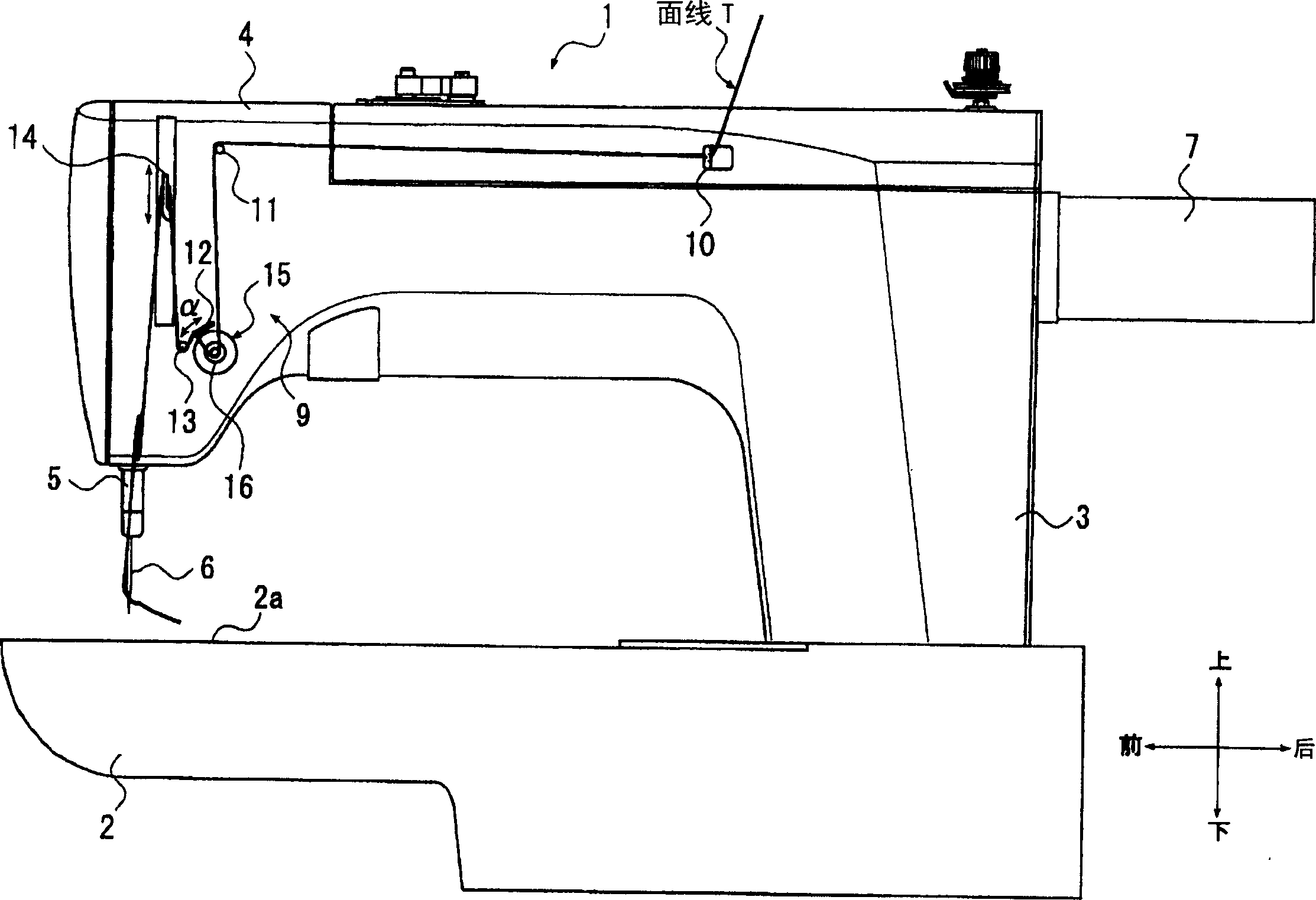
[0033] figure 1 The shown sewing machine 1 has the basic structure of a sewing machine that applies flat seams to a sewn object. That is, the sewing machine 1 has: a table portion 2 having a substantially horizontal machine table surface 2a, a vertical body portion 3 erected at the rear end portion of the table portion 2, and The machine head 4 protruding slightly parallel to the front, the needle bar 5 protruding downward from the front end of the machine head 4, the machine needle 6 installed on the lower end of the needle bar 5, the The semi-rotary rotary hook (not shown in the figure) of the inner space, the main motor 7 as the driving source of the sewing action supported on the machine head 4 frame, and the operation panel 48 for various data input ( Figure 5 ) and the overall co...


PUM


Abstract

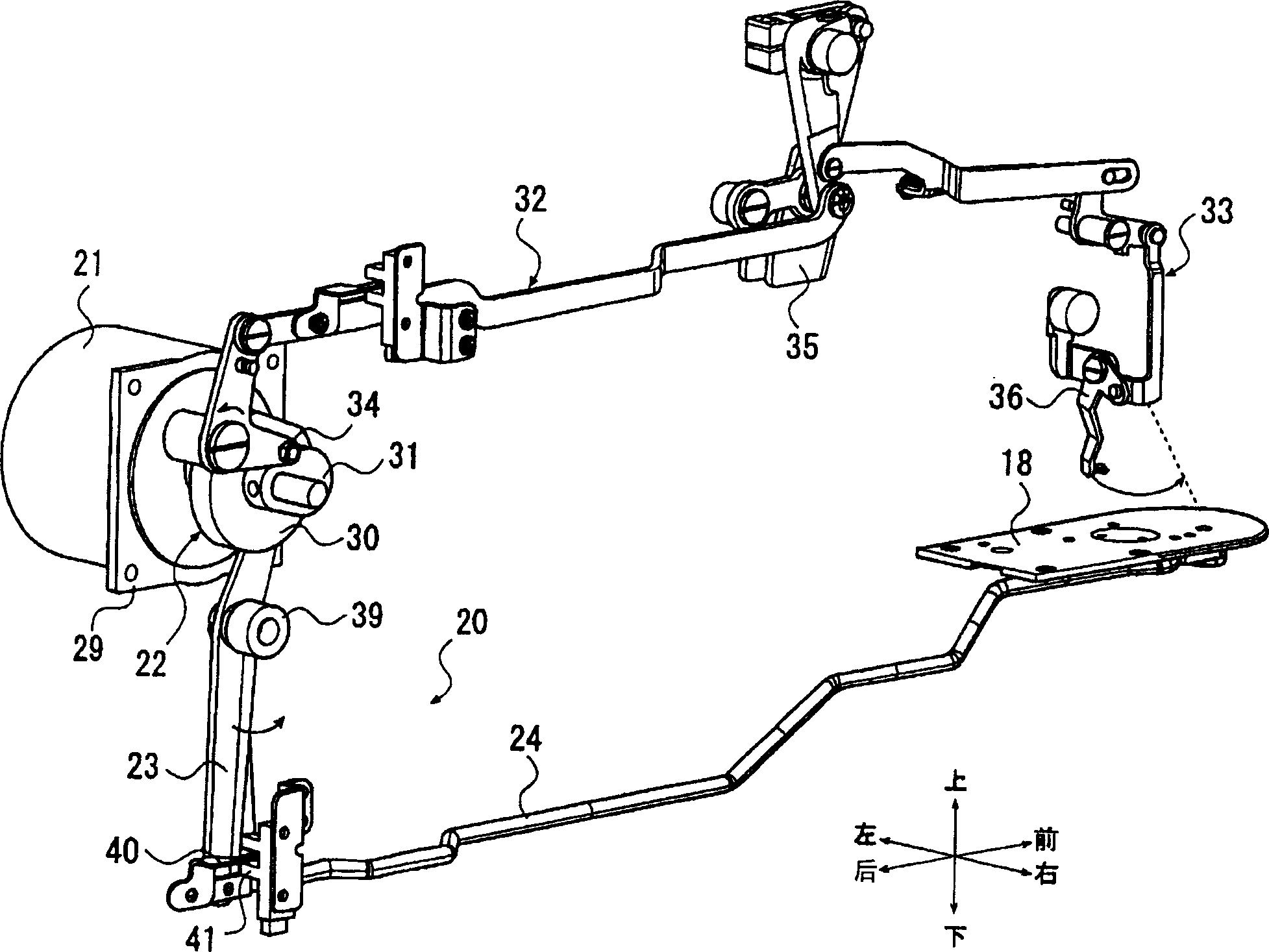
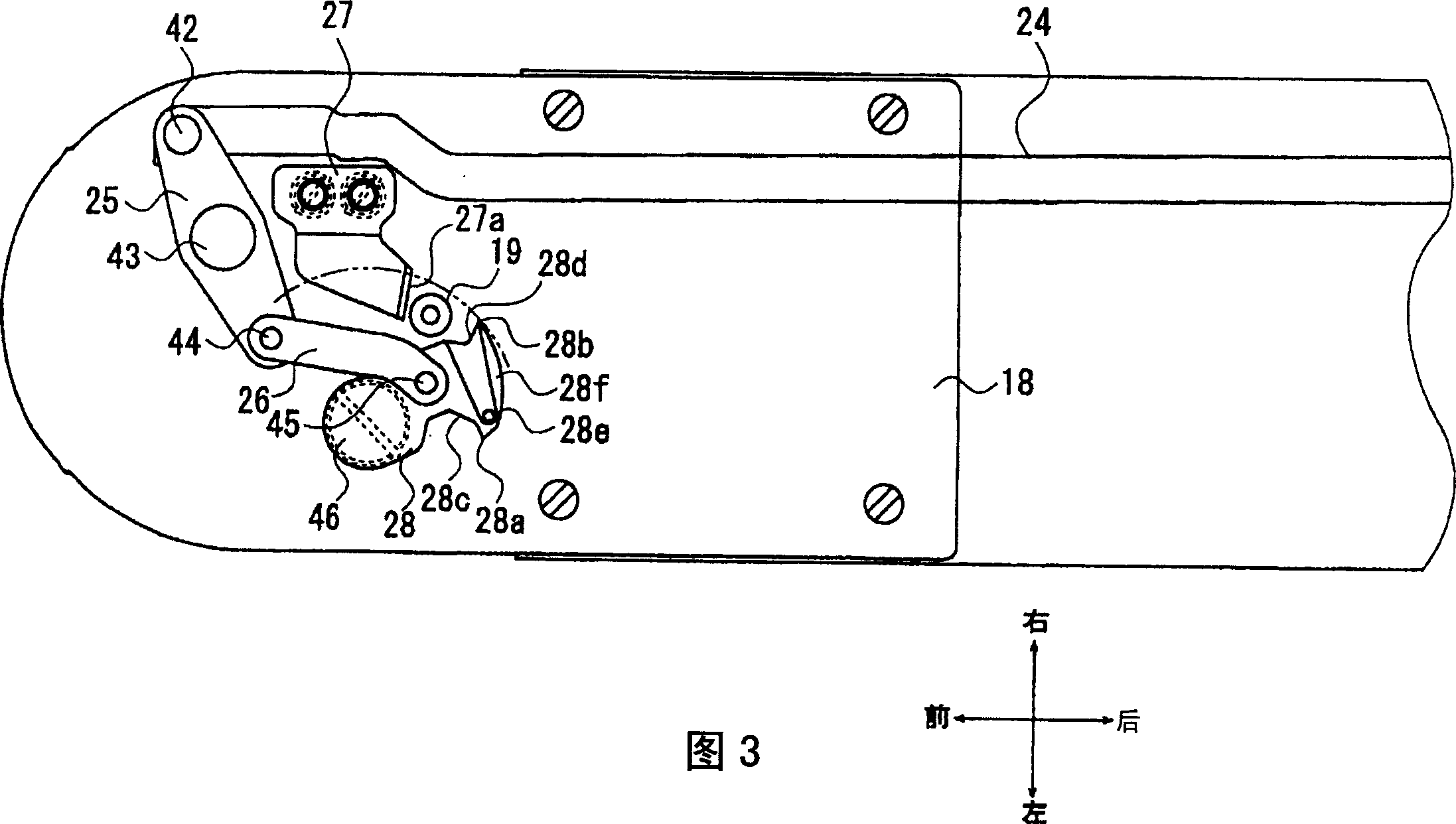
The patent relates to a sewing machine 1 in which a needle thread loop 101 is formed by the co-operation of a needle 6 and a semi-rotating shuttle to perform lock stitch. This sewing machine 1 includes a needle thread take-up lever 14 for taking up the needle thread loop 101, a main shaft motor 7 for driving the needle 6 and the needle thread take-up lever 14, a fixed knife 27 fixed in the vicinity of the semi-rotating shuttle, a movable knife 28 capable of freely approaching and separating from the fixed knife 27, a pulse motor 21 for driving the movable knife 28, and a control device 8 for controlling the pulse motor 21 and the main shaft motor 7. The movable knife 28 is stopped immediately before the movable knife 28 meets the fixed knife 27 at the final stitch under the control of the control device 8, and then the needle thread take-up lever 14 is raised and stopped. After that, the movable knife 28 is moved to cut the needle thread and the bobbin thread with the fixed knife 27. The sewing machine is capable of stabilize the so-called remaining length of a needle thread without lengthening the time required for cutting the needle thread.

Description

technical field [0001] The present invention relates to a sewing machine having a movable cutter for cutting noodle threads, a fixed cutter, and a cutter drive mechanism for driving the movable cutter, and particularly relates to a method for combining the above-mentioned drive mechanism with a so-called sewing drive source. Set of sewing machines. Background technique [0002] In previous sewing machines, the power of the main motor rotating the main shaft is transmitted to the needle and the thread take-up lever on the machine head through the main shaft, so that the needle and the thread take-up lever can move up and down. In addition, the power of the main motor is also The hook is driven by the lower shaft being transmitted to the hook inside the machine. [0003] In addition, it is well known that conventional sewing machines have an upper thread cutting device for cutting the upper thread. The upper thread cutting device has a fixed cutter fixed close to the rotary ...

Claims


Application Information

Patent Timeline
IPC IPC(8): D05B65/02D05B19/12D05B49/00D05B65/00D05B73/12
CPCD05B19/12D05B73/12D05B65/00D05B49/00D05B19/00
Inventor 日塔隆皆川忠义
Owner JUKI CORP
Why Eureka
Try Eureka