
Method for determining local antenna

A kind of antenna and local technology, applied in the direction of measuring device, magnetic resonance measurement, medical science, etc., can solve the problem of inaccurate determination of antenna position, achieve the effect of small error rate and improve accuracy

Inactive Publication Date: 2003-09-03
SIEMENS AG
View PDF3 Cites 4 Cited by
  • Summary
  • Abstract
  • Description
  • Claims
  • Application Information

AI Technical Summary

Problems solved by technology

If this is not the case, the determination of the antenna position will be inaccurate

Method used


Image

  • Method for determining local antenna
  • Method for determining local antenna
  • Method for determining local antenna

Examples


Embodiment Construction

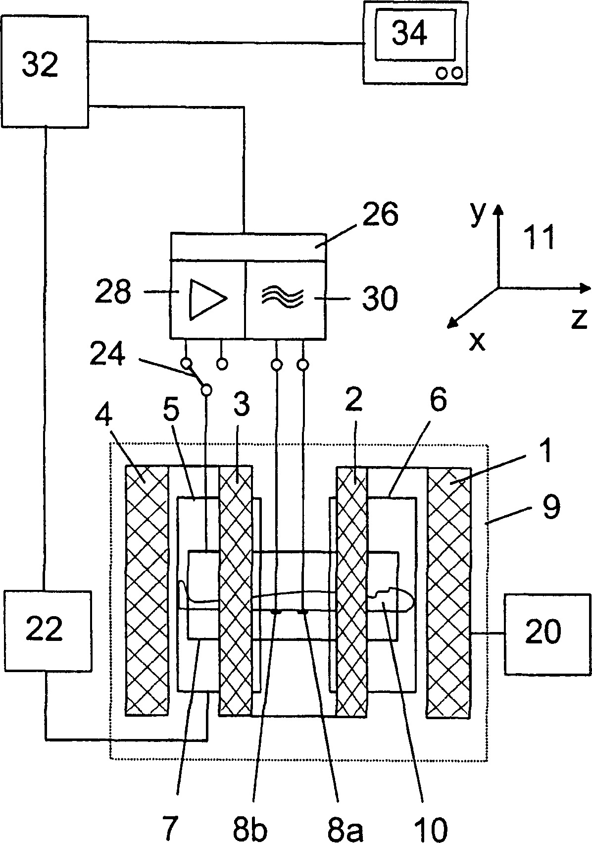
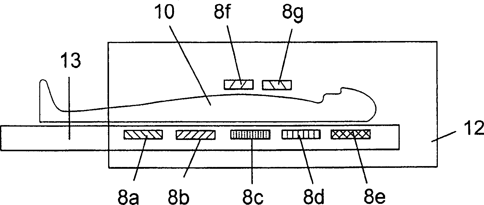
[0022] figure 1 An overview of a magnetic resonance system is shown, with which anatomical cross-sectional images and angiograms of the human body can be generated and functional examinations can also be performed. The magnetic resonance system comprises coils 1 to 4 which generate an approximately uniform basic magnetic field of high field strength in the axial direction in the examination volume. In medical diagnostic applications, the body region of the patient 10 to be examined is located in this examination space. A gradient coil system for generating an independent additional magnetic field likewise in the direction of the basic magnetic field is assigned to the examination space. As gradient magnetic fields, these additional magnetic fields have mutually perpendicular magnetic field gradients in the directions x, y and z according to the right-handed coordinate system 11 . figure 1 For the sake of clarity, only gradient coils 5 and 6 are shown in , which are a pair of...


PUM


Abstract

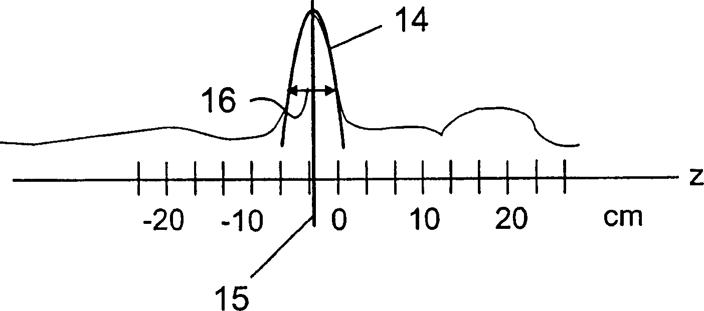
The patent relates to a method for determining the position of at least one local antenna in an examination space of a magnetic resonance system, wherein magnetic resonance signals emitted by a body arranged in the examination space are received by the at least one local antenna location-encoded in at least one coordinate direction, intensity values that are spatially resolved in the coordinate direction are generated from the received magnetic resonance signals, and the position of the local antenna in the coordinate direction is determined from a curve of the intensity values along the coordinate direction, the intensity values having been subjected as needed to post-processing. The determination of the position of the local antenna ensues by adapting a function to the curve of the intensity values, the function being manipulable to approximate the shape of a sensitivity profile of the local antenna, and the position of a maximum of the adapted function is utilized as the position of the local antenna. A noise-insensitive determination of the position of local antennas with high precision is achieved.

Description

technical field [0001] The invention relates to a method for determining the position of at least one local antenna in an examination area of ​​a magnetic resonance system, wherein the local antenna receives magnetic resonance reflected by a human body arranged in the examination area and coded in at least one coordinate direction. Signals from the received magnetic resonance signals generate position-resolved intensity values ​​in this coordinate direction and determine the position of the local antenna in this coordinate direction from the optionally reprocessed intensity value curve along this coordinate direction. Background technique [0002] Magnetic resonance tomography is a well-known technique for acquiring images inside a living subject. For magnetic resonance tomography, a stable, relatively homogeneous basic magnetic field is generated from the basic magnetic field. During the recording of the magnetic resonance images, rapidly switching gradient magnetic fields...

Claims


Application Information

Patent Timeline
Patent Type & Authority Applications(China)
IPC IPC(8): G01R33/3415
CPCG01R33/3415
Inventor 海科·迈耶汪坚敏
Owner SIEMENS AG
Learn More