

Gas connecting structure of double fuel cell sets
A fuel cell stack and fuel cell technology, which is applied to fuel cell components, fuel cells, fuel cell additives, etc., can solve problems such as insufficient fuel utilization, and achieve the effect of saving fuel consumption
- Summary
- Abstract
- Description
- Claims
- Application Information
AI Technical Summary
Problems solved by technology
Method used
Image

Examples
Embodiment Construction
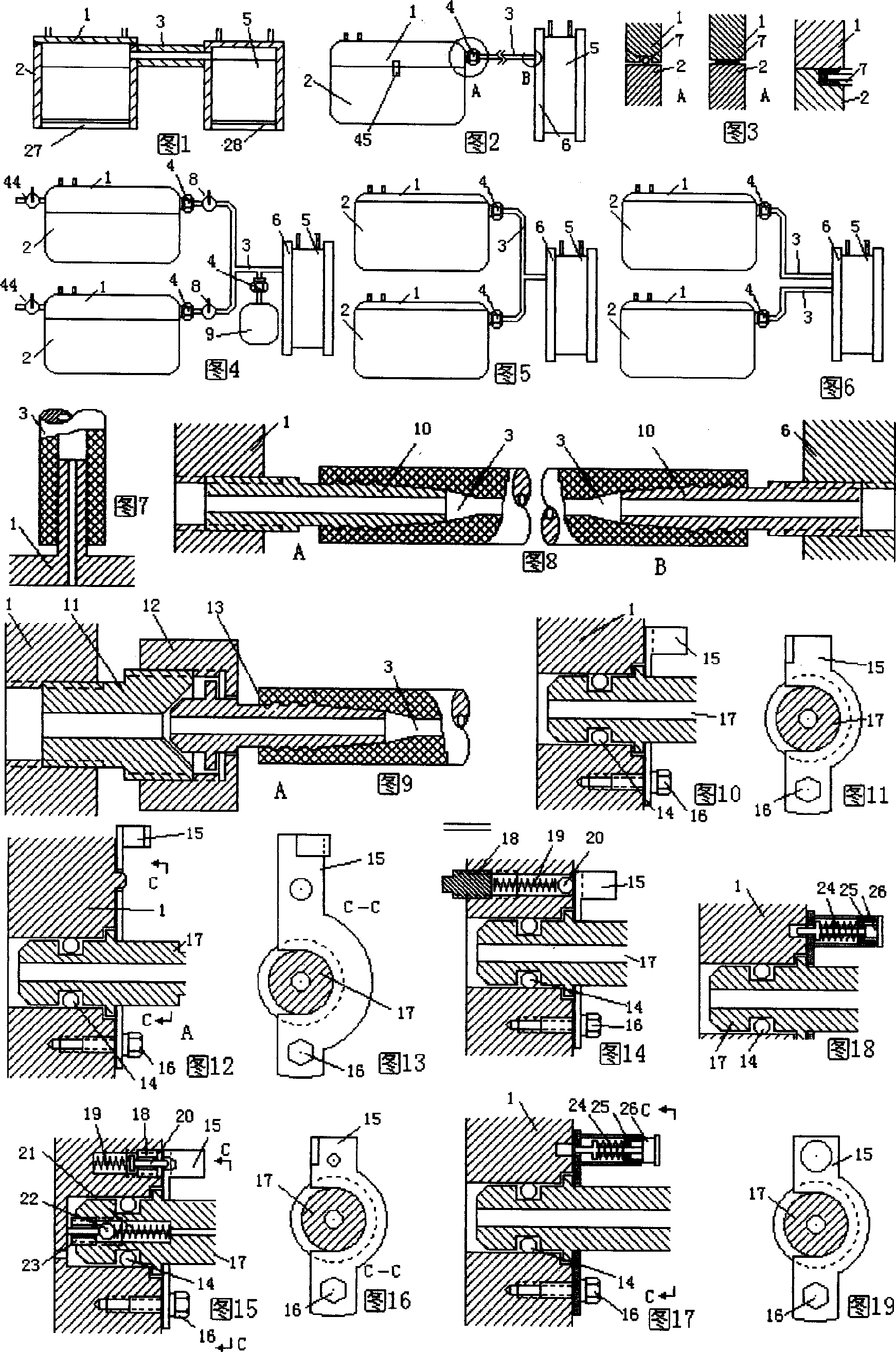
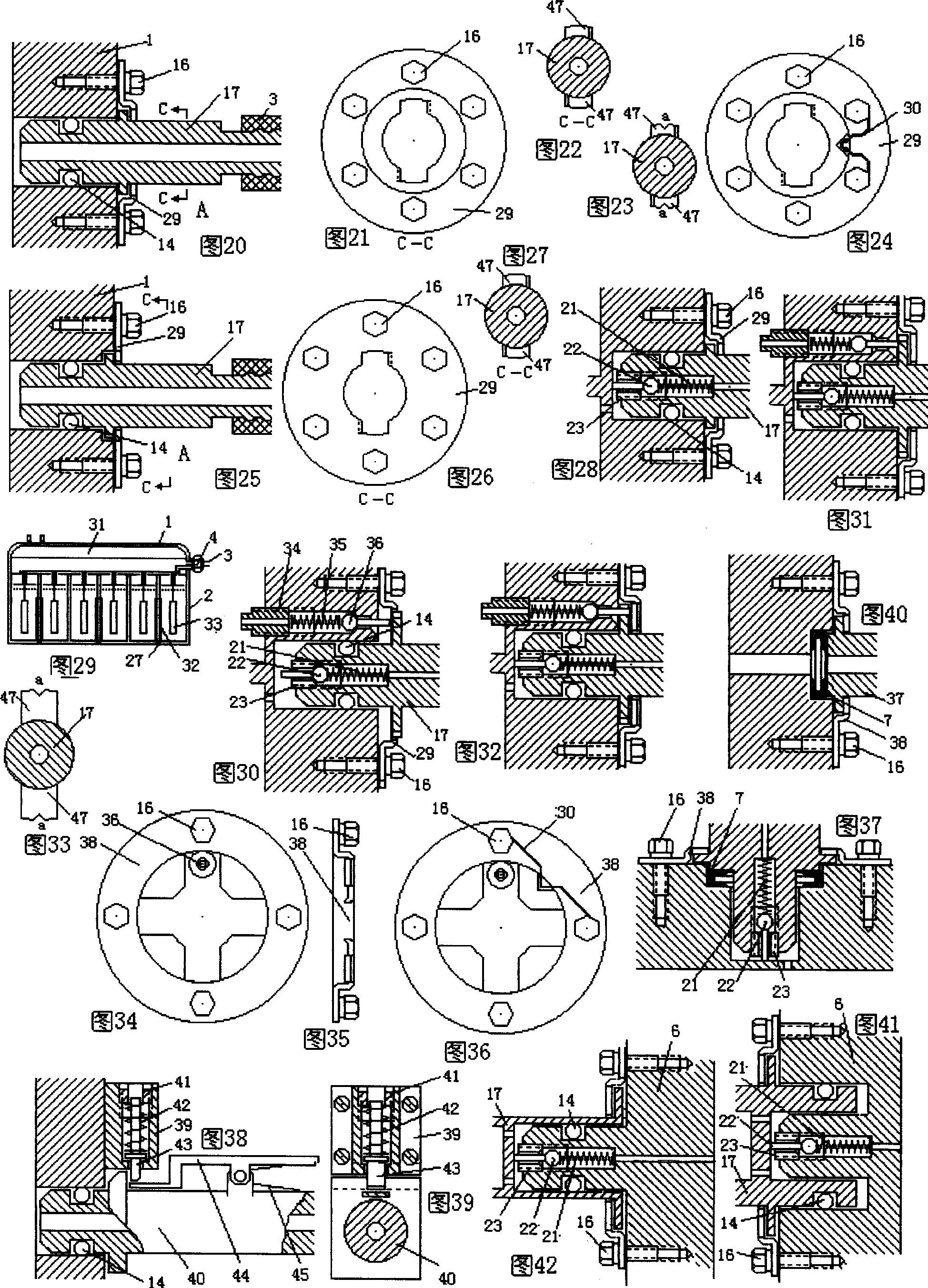
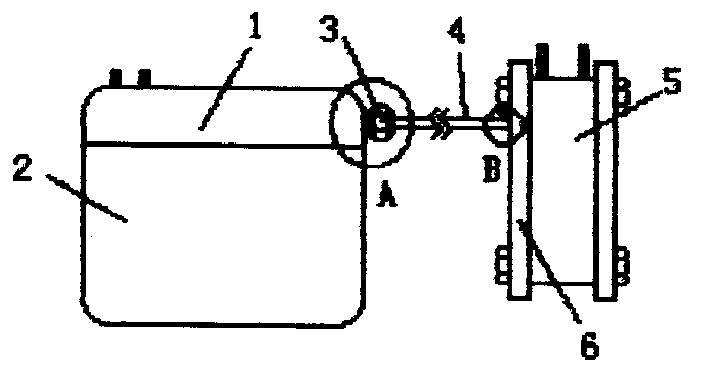
[0025] In Fig. 1: the "metal-air" fuel cell cover (1) is hermetically connected with the "metal-air" fuel cell casing (2), and one end of the gas channel (3) is connected to the "metal-air" fuel cell cover (1) Or on the housing (2), the other end of the gas channel (3) is fixedly connected to the hydrogen fuel input port of the hydrogen-oxygen fuel cell (5). The hydrogen gas generated during the power generation process of the "metal-air" fuel cell is confined in the casing by the sealing structure of the battery casing, and the generated hydrogen is sent to the hydrogen-oxygen fuel cell through the gas channel for further power generation.
[0026] In Fig. 2 and Fig. 3: the "metal-air" fuel cell cover (1) and the "metal-air" fuel cell housing (2) are fastened by the cover buckle (45), and the "metal-air" fuel cell cover (1 ) and the "metal-air" fuel cell shell (2) are sealed with a tight element (7) so that it will not leak. The gas channel (3) is connected with the "metal-a...
PUM
 Abstract
Description
Claims
Application Information