

Firewood-burning type waste-heat utilization continuous fixation tea strip tidying machine with electric hot air
A technology of finishing machine and electric hot air, applied in air heaters, fluid heaters, tea treatment before extraction, etc., can solve problems such as uneven finishing and insufficient aroma of finished tea, and achieve low fuel consumption and low energy costs , easy-to-operate effects
- Summary
- Abstract
- Description
- Claims
- Application Information
AI Technical Summary
Problems solved by technology
Method used
Image

Examples
Embodiment
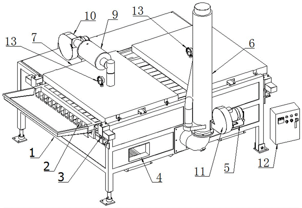
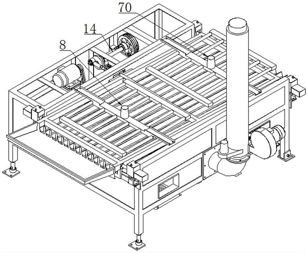
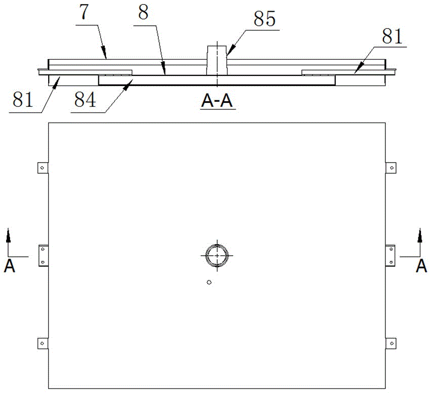
[0028] see Figure 1 to Figure 8 , a wood-fired waste heat utilization continuous finishing machine with electric hot air, including a frame 1, a tank 2, a roller assembly 3, a first hot air cover 7, a first hot air distributor 8, and an electric hot air generator 9 , the first blower fan 10 and the transmission device 14 . The frame 1 is a rectangular parallelepiped frame structure, four corners of the bottom are provided with four supporting legs, the upper plane is an inclined surface along the length direction, and a group of roller assemblies 3 are respectively installed at both ends of the length direction of the inclined surface, each group of roller assemblies 3 There are two rollers, and these two rollers are respectively arranged on both sides of the width direction of the inclined surface; the tank 2 is provided with two sets of slide bars, and each set of slide bars is correspondingly connected to a set of roller assemblies 3; The transmission device 14 is located...
PUM
| Property | Measurement | Unit |
|---|---|---|
| Thickness | aaaaa | aaaaa |
Abstract
Description
Claims
Application Information