Absorption-type refrigerator

An absorption refrigerator and absorption liquid technology, applied in the direction of adsorption machines, refrigerators, refrigeration and liquefaction, etc., can solve many problems, such as corrosion of heat exchangers, and drop in exhaust gas temperature

Inactive Publication Date: 2003-10-15
SANYO ELECTRIC CO LTD +1
View PDF0 Cites 3 Cited by
  • Summary
  • Abstract
  • Description
  • Claims
  • Application Information

AI Technical Summary

Problems solved by technology

[0005] However, in the above-mentioned conventional absorption refrigerating machine, since the flow control valve 25 is provided on the absorption liquid pipe (detour absorption liquid pipe) 11B detoured in the second exhaust gas heat recovery unit 24, even if the flow control valve 25 is fully opened, , the amount of dilute absorption liquid that flows to the second exhaust gas heat recovery device 24 through the absorption liquid pipe 11A is not small
[0006] Therefore, when the temperature of the exhaust gas and the dilute absorption liquid are very low at the start of operation, even if the flow control valve is fully opened, sometimes the exhaust gas temperature will drop excessively, and the water vapor contained in the exhaust gas will condense and condense, causing corrosion and heat exchange. Therefore, it is necessary to provide an absorption refrigerator having a structure that does not cause such problems.

Method used


Image

  • Absorption-type refrigerator
  • Absorption-type refrigerator
  • Absorption-type refrigerator

Examples


no. 1 example

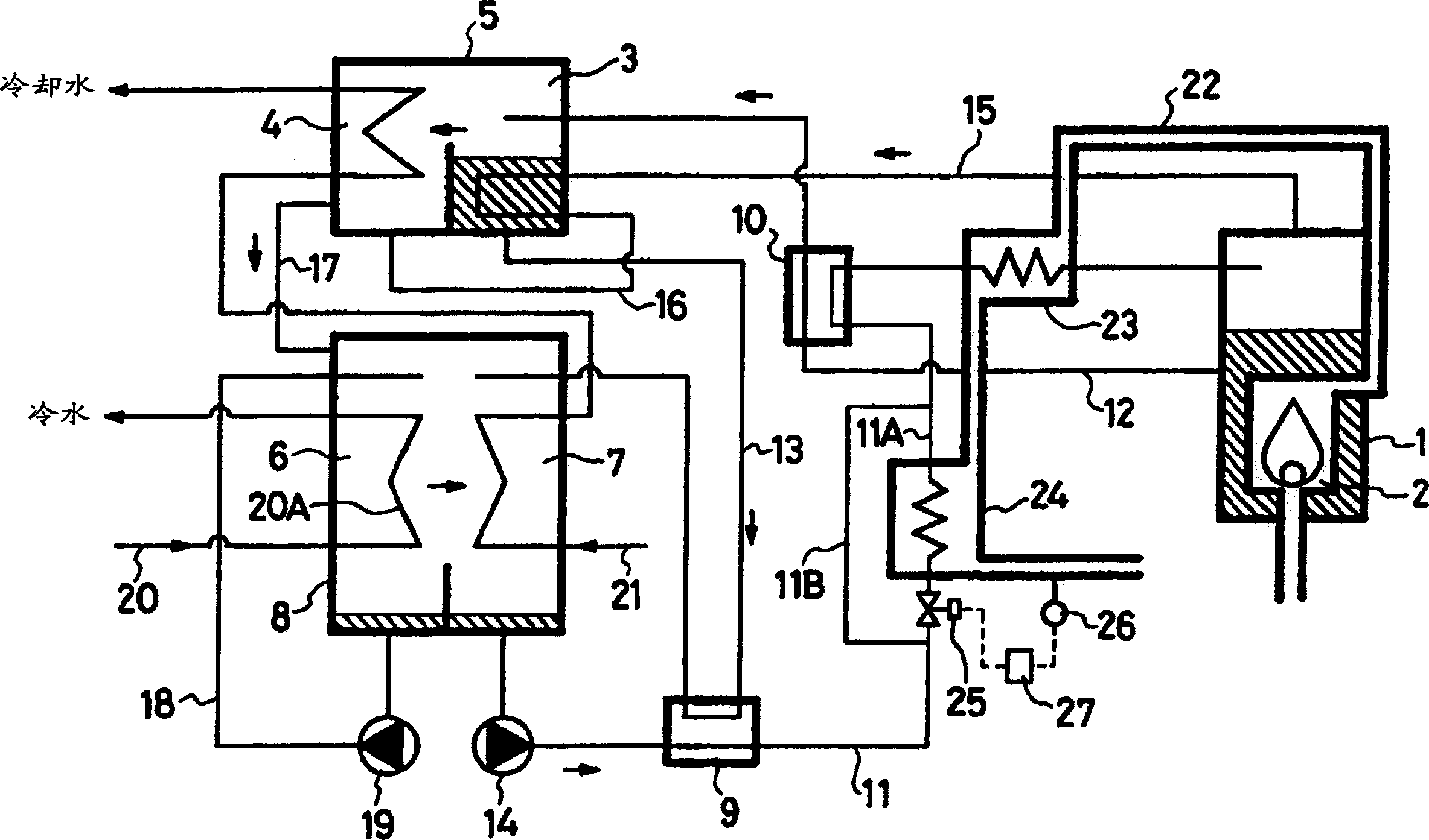
[0016] according to figure 1 A first embodiment of the present invention will be described. 1 is a high-temperature regenerator, which is configured such that the heat of the gas burner 2 using city gas as fuel is used to heat the absorption liquid and evaporate and separate the refrigerant. 3 is a low-temperature regenerator, 4 is a condenser, and 5 is a storage low-temperature regenerator. 3 and the high-temperature shell of the condenser 4, 6 is an evaporator, 7 is an absorber, 8 is a low-temperature shell for accommodating the evaporator 6 and the absorber 7, 9 is a low-temperature heat exchanger, 10 is a high-temperature heat exchanger, 11 ~13 is the absorption liquid pipe, 14 is the absorption liquid pump, 15~18 is the refrigerant pipe, 19 is the refrigerant pump, 20 is the cold water pipe, 21 is the cooling water pipe, 22 is the exhaust gas discharged from the gas burner 2. Air pipe, 23 is a first exhaust gas heat recovery device, 24 is a second exhaust gas heat recov...

no. 2 example

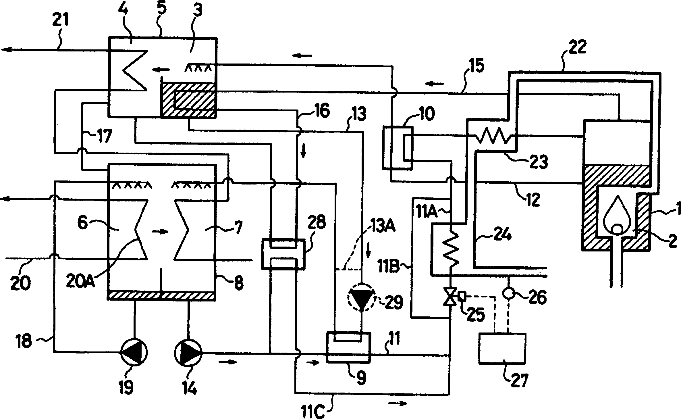
[0028] according to figure 2 , the second embodiment of the present invention will be described. In the absorption refrigerator of this second embodiment, in figure 1 A refrigerant heat recovery unit 28 is added to the piping structure of the absorption refrigerating machine of the first embodiment shown.

[0029] In the refrigerant heat recovery device 28, the refrigerant from the low-temperature regenerator 3 to the condenser 4 is heated, that is, the intermediate absorption liquid in the low-temperature regenerator 3, and the refrigerant evaporated, separated and condensed is supplied with the refrigerant from the low-temperature regenerator 3. The absorber 7 uses the absorption liquid pump 14 to transport part of the dilute absorption liquid to the high temperature regenerator 1, that is, the dilute absorption liquid flowing in the absorption liquid pipe (dilute absorption liquid branch pipe) 11C detoured in the low temperature heat exchanger 9, and Make it perform hea...

no. 3 example

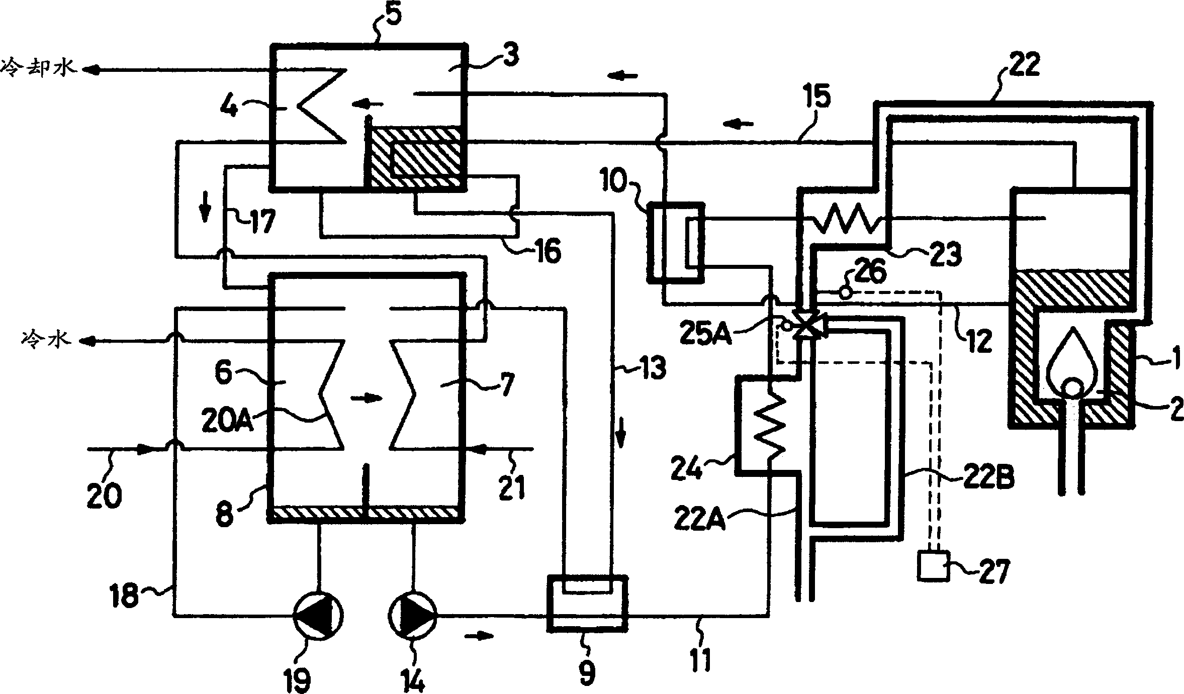
[0038] according to image 3 A third embodiment of the present invention will be described. In the absorption refrigerating machine of this example, the exhaust pipe (detour exhaust pipe) 22B detoured in the second exhaust gas heat recovery unit 24 is provided instead of the figure 1 The absorption liquid pipe (detour absorption liquid pipe) 11B equipped in the absorption refrigerator of the first embodiment shown, and the exhaust pipe 22A and the exhaust pipe (detour exhaust pipe) via the second exhaust gas heat recovery unit 24 ) 22B is provided with a switching valve 25A instead of the flow control valve 25.

[0039] The temperature sensor 26 is provided on the exhaust pipe 22 on the upstream side of the branch portion of the exhaust pipe 22A and the exhaust pipe (detour exhaust pipe) 22B. Other piping structures are the same as those of the first embodiment.

[0040] In the absorption refrigerating machine of this third embodiment, when the temperature sensor 26 detect...


PUM


Abstract

The invention provides an absorption refrigerating machine to prevent any condensation of steam contained in exhaust gas even in a starting operation or a partially loaded operation having a mechanism to collect the heat from the exhaust gas. An absorption refrigerating machine has first and second exhaust gas heat collectors 23 and 24, an absorbent pipe (a bypassing absorbent pipe) 11B to allow dilute absorbent from a low-temperature heat exchanger 9 to flow in a bypassing manner around the exhaust gas heat collector 24, a flow rate control valve 25 provided on an absorbent pipe 11A leading to the second exhaust gas heat collector 24, and a controller 27 to control the opening of the flow rate control valve 25 so that a temperature sensor 26 continuously detects the predetermined temperature (for example, 100 DEG C.) higher than the dew point of the exhaust gas.

Description

technical field [0001] This invention relates to absorption refrigerators. Background technique [0002] Such as Figure 5 As shown, it is well known that the existing absorption refrigerating machine is to try to make the waste gas discharged from the gas burner 2 which heats and boils the dilute absorption liquid of the high temperature regenerator 1 sequentially sent to the first waste gas heat recovery device 23, which is arranged in the absorption liquid pipe Between the high-temperature heat exchanger 10 of 11 and the high-temperature regenerator 1; the second waste gas heat recovery device 24, which is arranged between the low-temperature heat exchanger 9 and the high-temperature heat exchanger 10, makes the transfer from the absorber 7 to the high-temperature regenerator As the temperature of the dilute absorbing liquid in 1 rises, the amount of heating necessary for the gas burner 2 decreases, reducing fuel consumption. [0003] That is to say, in the absorption re...

Claims


Application Information

Patent Timeline
Patent Type & Authority Applications(China)
IPC IPC(8): F25B15/00F25B15/06
CPCY02B30/62Y02P80/15Y02A30/27F25B15/00
Inventor 古川雅裕山崎志奥伊良皆数恭镰田泰司
Owner SANYO ELECTRIC CO LTD
Why Eureka
Try Eureka