
Convective motor unit of microwave oven

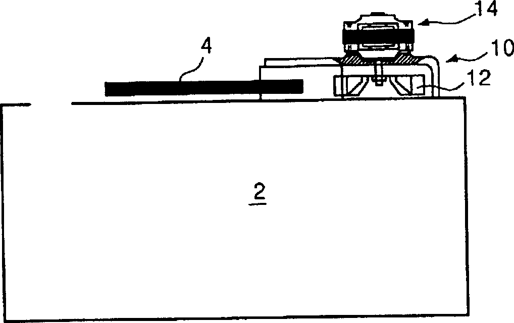
A technology of motor components and microwave ovens, which is applied in the field of microwave ovens, can solve problems such as noise, and achieve the effect of preventing noise and vibration

Inactive Publication Date: 2003-11-26
LG ELECTRONICS (TIANJIN) APPLIANCES CO LTD
View PDF0 Cites 1 Cited by
  • Summary
  • Abstract
  • Description
  • Claims
  • Application Information

AI Technical Summary

Problems solved by technology

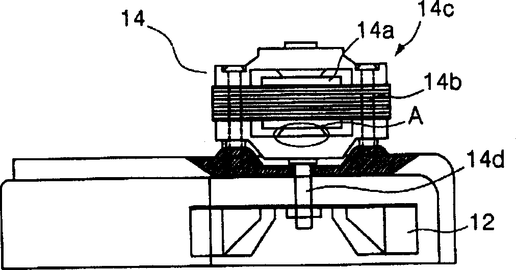
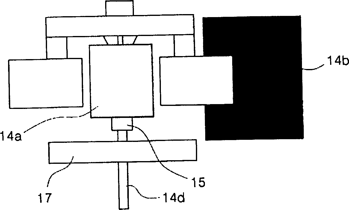
[0006] However, when the above-mentioned convection motor assembly 10 is installed vertically, since the rotating member will move up and down in the gap between the above-mentioned film washer 15 and the bracket 17, noise may occur due to the contact between the above-mentioned rotating member and the above-mentioned bracket 17 The problem

Method used


Image

  • Convective motor unit of microwave oven
  • Convective motor unit of microwave oven
  • Convective motor unit of microwave oven

Examples


Embodiment Construction

[0018] Refer to the following Figure 4 The present invention will be described in more detail.

[0019] As shown in the figure, the motor assembly of the present invention is composed of a rotating member 20 and a fixed member including a coil 30 . Since the lower end of the rotating member 20 is connected to the rotating shaft 22, the fan can be rotated. In addition, the drawing part 29 in the figure refers to the core used to concentrate the magnetic flux generated by the above-mentioned coil 30 .

[0020] The lower end of the bracket 26 has a bearing (omitted in the figure) for supporting the above-mentioned rotating shaft 22 to make it rotate smoothly, and there is a certain interval between the bracket 26 and the above-mentioned rotating member 20 .

[0021] In the present invention, the upper end of the above-mentioned rotating shaft 22 is equipped with a lubricating slice 24a and a film washer 24b. That is, the above-mentioned lubricating section 24a and film washer...


PUM


Abstract

The convective motor assembly for microwave oven is installed vertically on the heating chamber, and includes fixing part with coil, rotating part, rotating shaft connected to the lower end of the rotating part, bracket with bearing for the rotating shaft, lubricating sheet of teflon and film spacer between the rotating part and the bracket.

Description

technical field [0001] The present invention relates to a microwave oven, more specifically, to a convection motor assembly for a microwave oven which utilizes a convection motor to circulate heat from a heater provided inside the microwave oven. Background technique [0002] In microwave ovens with microwaves as the main heat source, in order to solve the problem of single heat source due to microwave heating alone, microwave ovens with heaters inside have recently appeared. Such as figure 1 As shown, a heater 4 is arranged above the heating chamber 2 . In addition, on one side of the upper part of the heating chamber 2, a convection motor assembly 10 for circulating air is provided, which can circulate the air in the direction of the arrow shown in the figure. [0003] That is, the convection motor assembly 10 sucks the air inside the heating chamber, makes the air flow through the heater 4 , and returns the hot air (air heated by the heater) back into the heating chambe...

Claims


Application Information

Patent Timeline
IPC IPC(8): F24C7/02F24C15/32
Inventor 郑孝允崔武然
Owner LG ELECTRONICS (TIANJIN) APPLIANCES CO LTD
Learn More