
Steel cable tension mechanism for handle-type gear changer

A technology of tensioning mechanism and shifter, which is applied in the direction of bicycle gear transmission mechanism, mechanical equipment, bicycle accessories, etc., and can solve the problems affecting the weight and cost of the conversion device

Inactive Publication Date: 2003-12-17
SRAM
View PDF1 Cites 19 Cited by
  • Summary
  • Abstract
  • Description
  • Claims
  • Application Information

AI Technical Summary

Problems solved by technology

Considering the service life of these parts, they are designed to be rigid, which affects inter alia the weight and cost of the conversion device

Method used


Image

  • Steel cable tension mechanism for handle-type gear changer
  • Steel cable tension mechanism for handle-type gear changer
  • Steel cable tension mechanism for handle-type gear changer

Examples


Embodiment Construction

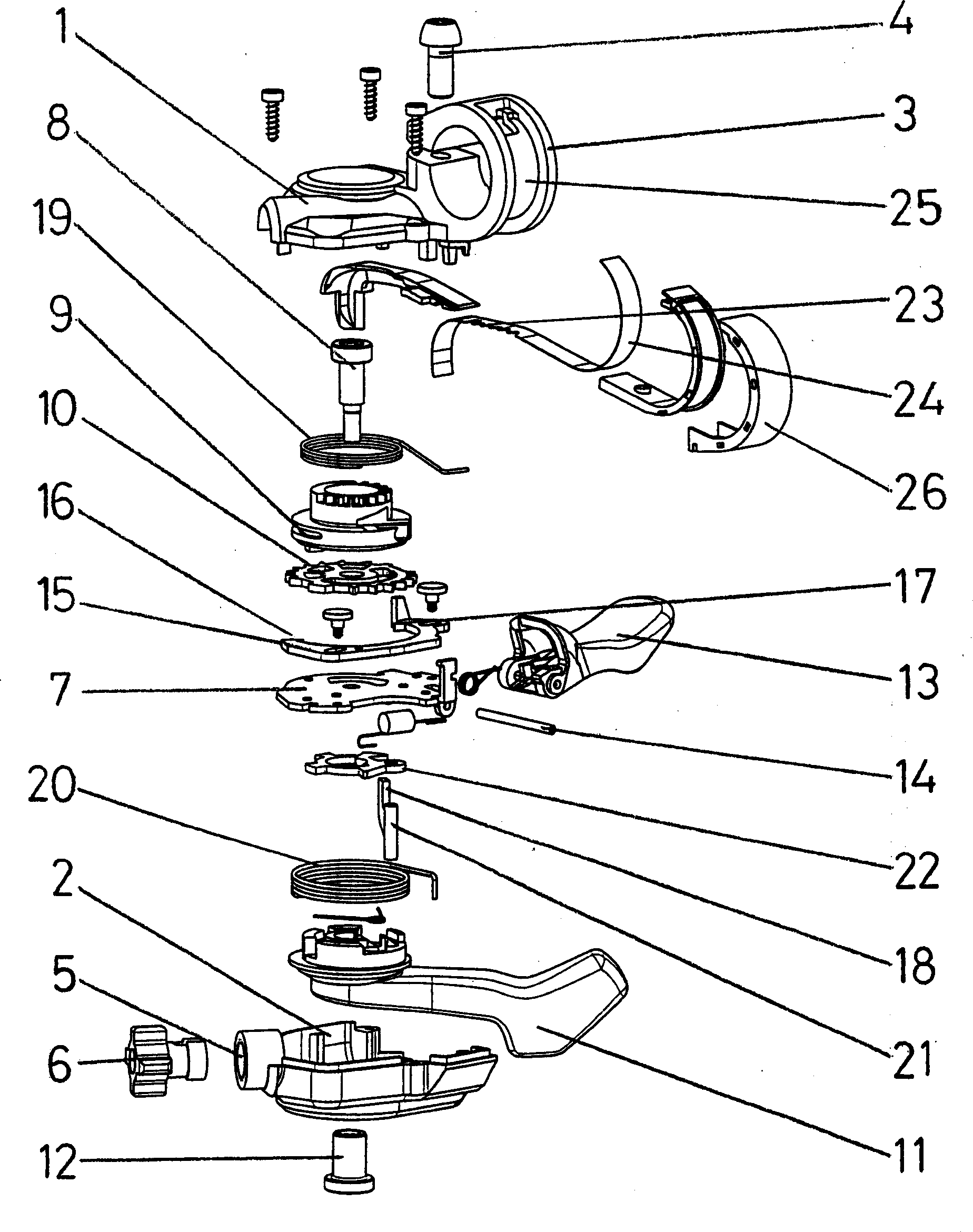
[0023] figure 1 The main components of a preferred embodiment of the trigger shifter are shown in an exploded view.

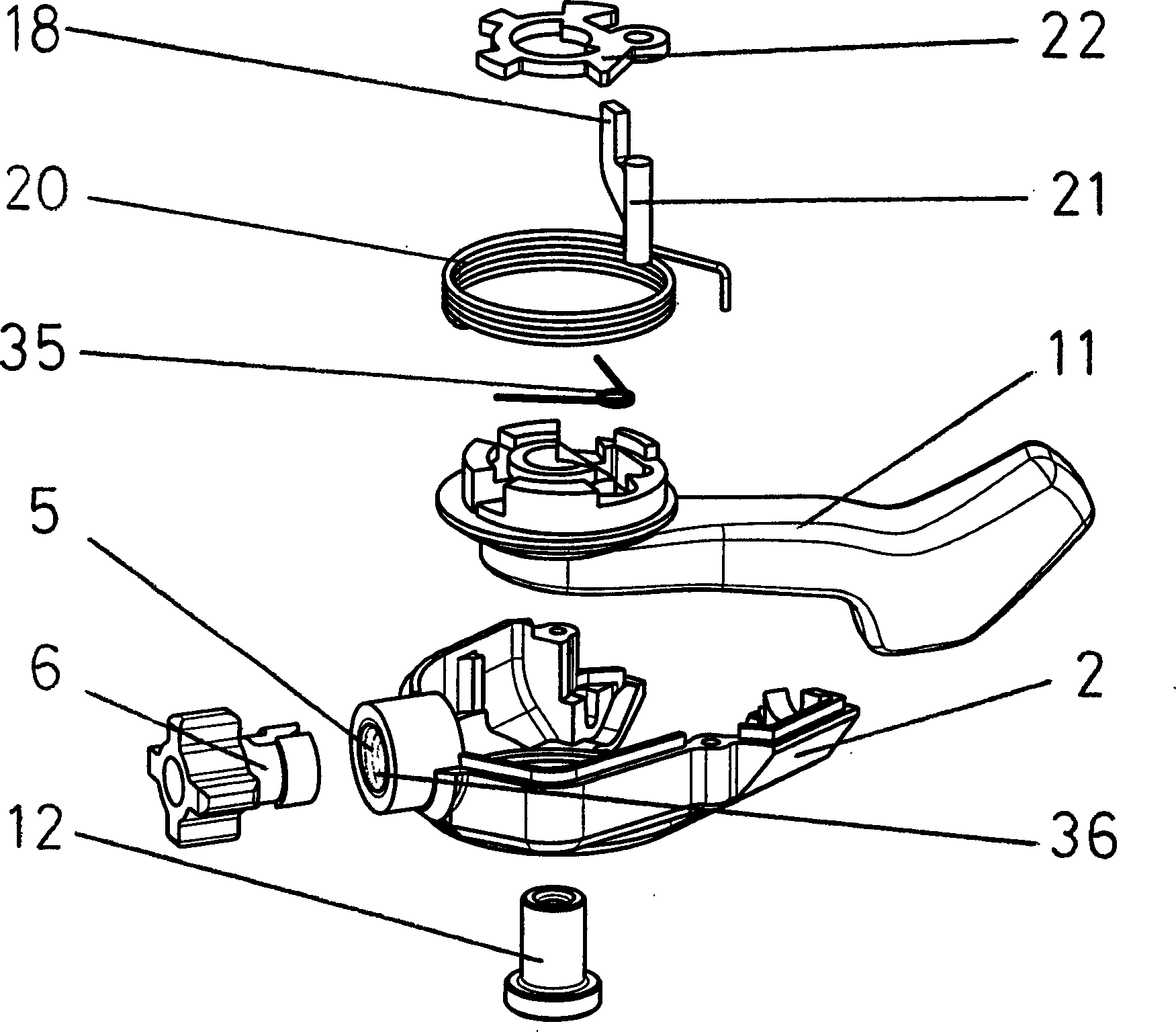
[0024]The shifter is composed of functional components, namely a release mechanism, a tension mechanism and a gear position display mechanism. These functional components are surrounded by a shifter housing 1 with an integrated control lever collar 3 and lining 2 . The shifter housing 1 is fastened to the control rod by means of a control rod fastening in the form of a control rod clamp 3 and a clamping screw 4 . On the insert 2 there is a thread 5 for accommodating an adjusting screw 6 which is required for the adjustment of the shift rod. The insert 2, including the thread 5, is made of plastic without any further subsequent machining.

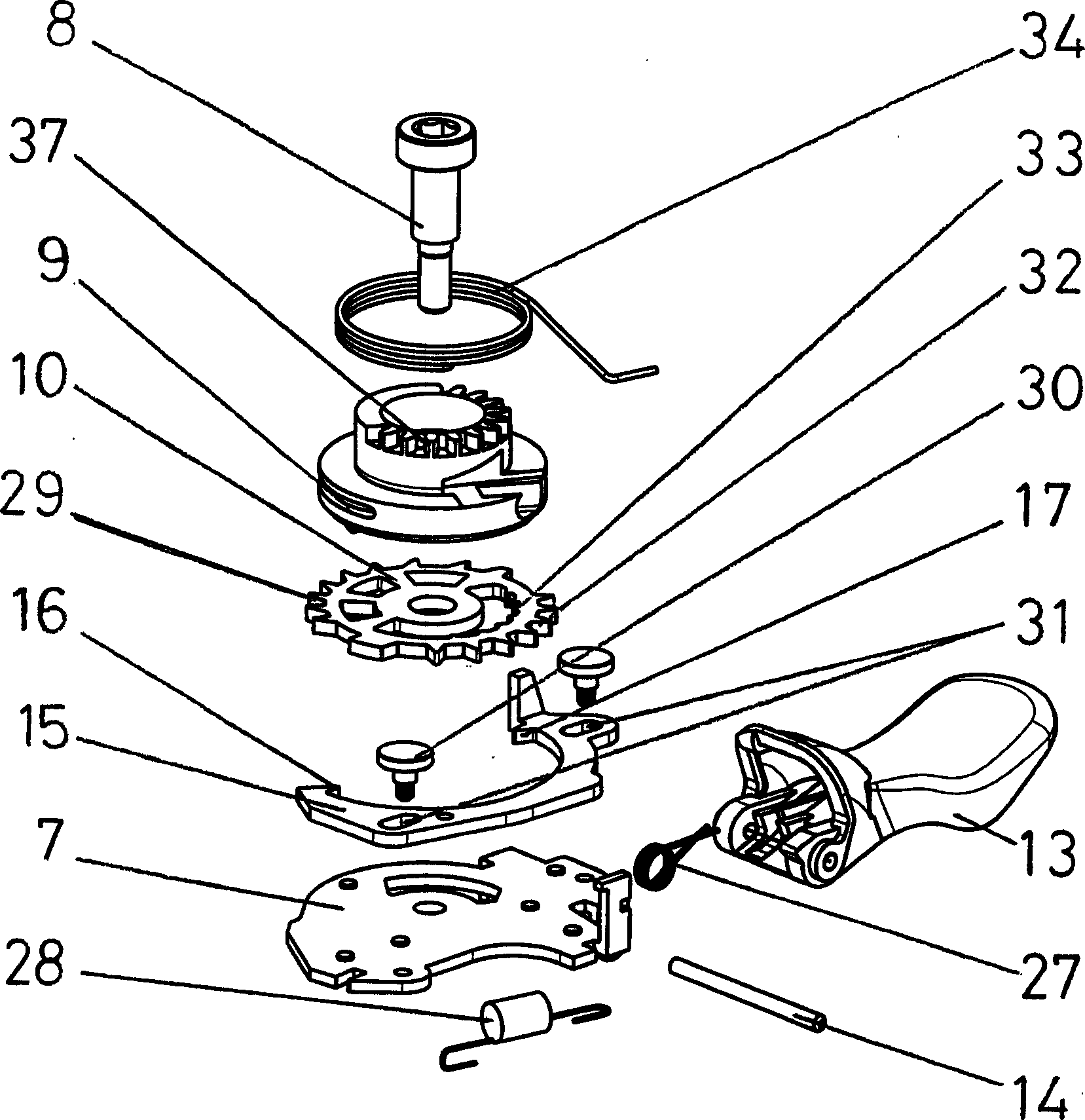
[0025] A release mechanism and tension mechanism are arranged around a support plate 7 and a central shaft 8 . On the shaft 8, the wire rope loop 9, the disc 10 and the operating part 11 are supported and they are fixed a...


PUM


Abstract

This invention relates to a trigger-switch with a pull-up, holding and release mechanism in level or rotation-grasp-switches to operate the bicycle gear-shifter. The switch is composed of a housing with integrated handle-bar-clamp and a pull-up-, holding, release and display mechanism. The tooth-segments, in which a pull-up-, holding and stop-claw is engaged respectively, necessary for the pull-up, holding and release-process are mounted in only one dish-shaped member. Thus a tooth-segment, preferably with inner tooth, is arranged inside of the circumference in an opening of the dish-element. The pull-up-movement is transferred over a slim pull-up-claw of the operation-element through the carrier-plate to the pull-up-tooth segment located inside of the dish-element. The actual gear-state is transferred over an elastic display-band, which combs in a tooth of the rope-spool, from there out around the handle-bar, along the handle-bar-clamp into the visible region of the rider. In order to improve the display-discrimination, a transparent cover of the display-band is formed as lens or amplifying glass. The switch mechanism is surrounded by a switch-housing and a casing-element composed of plastics. The receptacle of the adjusting-bolt for the gear-traction stress exists on this casing-element.

Description

technical field [0001] The invention relates to a shifting mechanism for a step shifter, which has a tensioning mechanism, a holding mechanism and a releasing mechanism, in particular to a tensioning, holding and releasing mechanism according to the preamble of claim 1 Wire rope tensioning positioning device for wire rope tension. The wire rope tensioning positioning device is used in a trigger shifter, for example, in a lever shifter or a turntable shifter for manipulating bicycle gear shifting. Background technique [0002] Stepper shifters are used to wind up and unwind a spring-pretensioned shift rod and return it to its original position after its operation. EPO361335B1 and DE19809113A1 disclose stepper or trigger shifters. [0003] The gear selectors shown each comprise two switching levers, one of which is used to tension or roll up the selector rod, and the other is used to release the retaining device or to release the spring-pretensioned selector rod. The tensio...

Claims


Application Information

Patent Timeline
Patent Type & Authority Applications(China)
IPC IPC(8): B62M25/04
CPCY10T74/20438Y10T74/214B62M25/045B62M25/04Y10T74/2136Y10T74/20287Y10T74/2028Y10T74/2133
Inventor R·维泽尔马丁·维斯
Owner SRAM
Learn More