Reciprocating motion type compressor using resonance

A reciprocating motion and compressor technology, applied in the field of compressors, can solve the problems of reduced speed, reduced amount of compressed and discharged refrigerant, and limited compressor efficiency, so as to achieve the effects of preventing loss, improving compression efficiency, and uniform speed

Inactive Publication Date: 2003-12-17
LG ELECTRONICS (TIANJIN) APPLIANCES CO LTD
View PDF0 Cites 3 Cited by
  • Summary
  • Abstract
  • Description
  • Claims
  • Application Information

AI Technical Summary

Problems solved by technology

[0011] However, when the conventional hermetic reciprocating compressor sucks the refrigerant into the compression space 12, when the piston 10 moves from the upper end TDP to the lower end BDP inside the cylinder 9,

Method used


Image

  • Reciprocating motion type compressor using resonance
  • Reciprocating motion type compressor using resonance
  • Reciprocating motion type compressor using resonance

Examples


Embodiment Construction

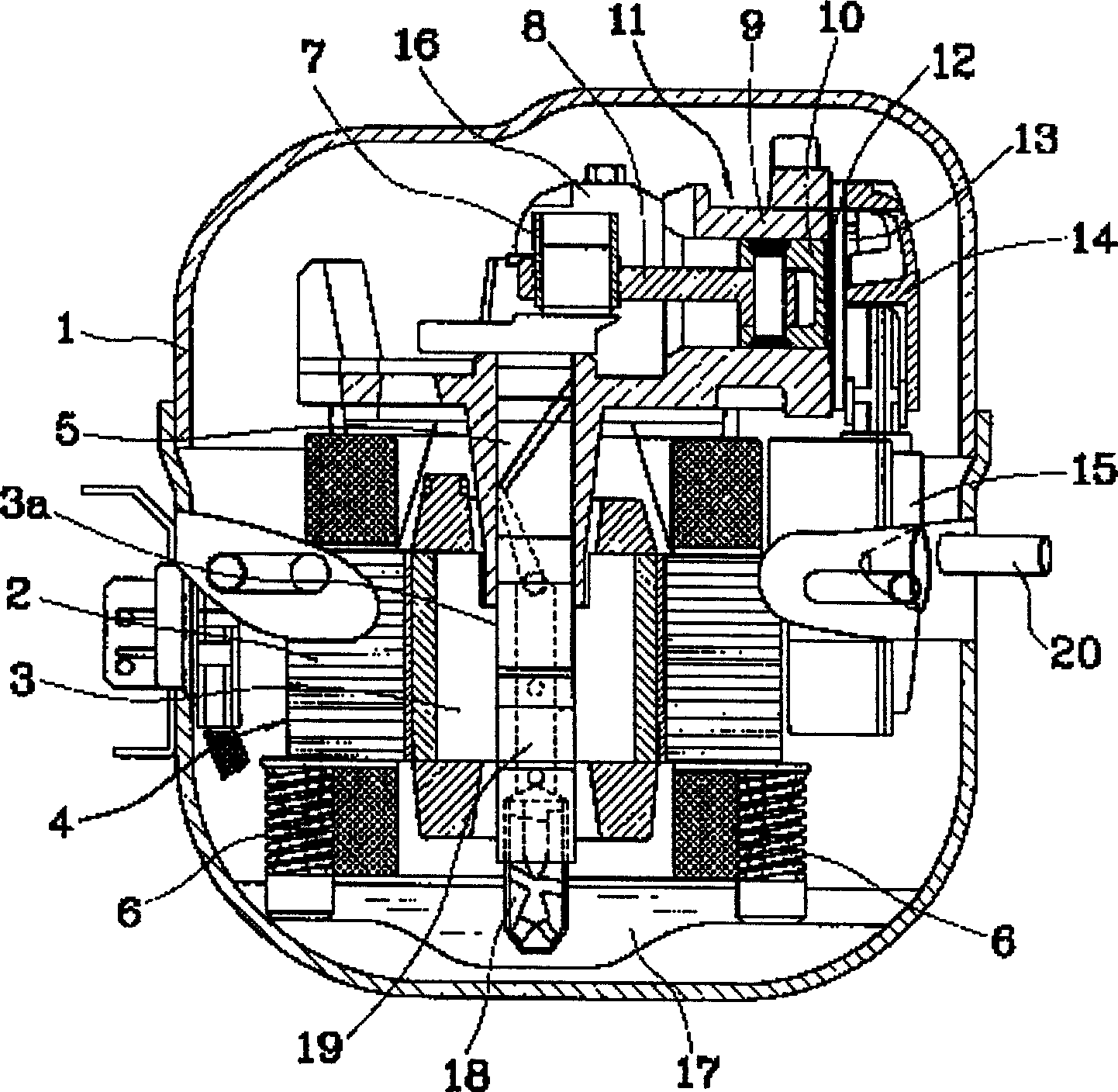
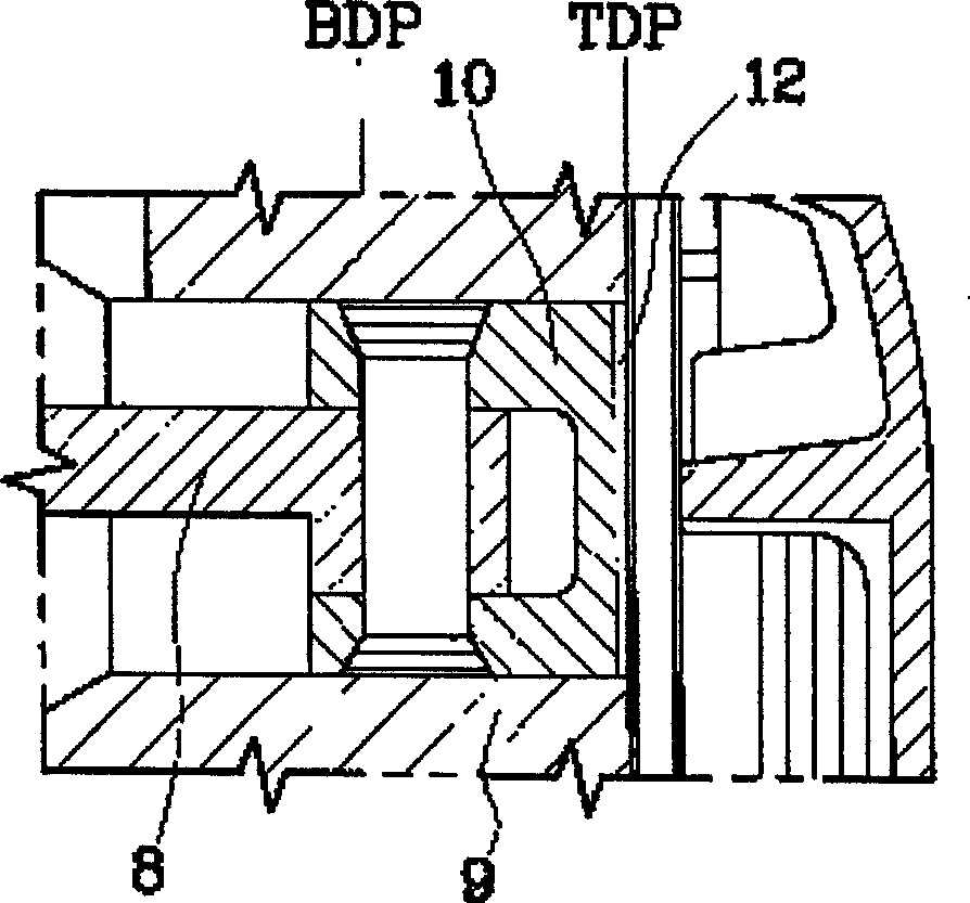
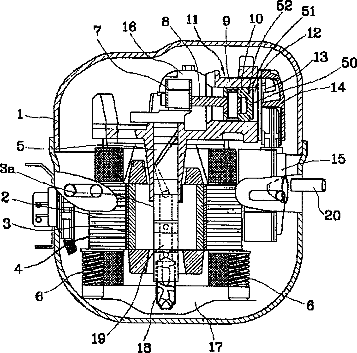
[0038] The reciprocating compressor utilizing resonance of the present invention will be further described in detail below in conjunction with the accompanying drawings and specific embodiments: image 3 It is a longitudinal sectional view of the structure of the reciprocating compressor utilizing the resonance of the present invention, Figure 4 is a partial sectional view of the installed state of the piston of the present invention, Figure 5 It is a perspective view of the structure of the piston of the present invention. As shown in the figure, the basic structure is the same as that of the conventional compressor, and the same parts are described with the same symbols.

[0039] A rotating part 4 composed of a stator 2 and a rotor 3 is installed in a closed container 1 having a closed space. The shaft of the rotor 3 is pressed into the hole 3a to press the rotating shaft 5, and the upper end of the rotating shaft 5 is inserted into the shaft supporting hole 6a. . In ord...


PUM


Abstract

A reciprocating compressor using resonance features that a piston cap less than internal diameter of cylinder is integrated on the end of piston to form a resonator. In the sucking procedure, the resonance of sucked cold medium takes place in said resonator for speeding up the piston and increasing the sucked cold medium. In the compression procedure, said resonance can make speed uniform to increase compression efficiency.

Description

technical field [0001] The invention relates to the field of compressors. Background technique [0002] In general, a compressor is a machine that sucks in fluid, compresses it, and discharges it. It consists of a rotating part that generates a driving force and a compression part that compresses the fluid using the driving force generated by the rotating part. According to the shape of the compression parts, it can be divided into hermetic rotary compressors, hermetic reciprocating compressors, and hermetic sleeve compressors. [0003] figure 1 It is a longitudinal sectional view of a reciprocating compressor structure in the prior art. [0004] As shown in the figure, the prior art reciprocating compressor has a closed container 1 with a closed space, and a rotating part 4 composed of a stator 2 and a rotor 3 is installed. The shaft pressing hole 3a in the center of the rotor 3 is pressed into the rotating shaft 5, and the upper end of the rotating shaft 5 is inserted i...

Claims


Application Information

Patent Timeline
IPC IPC(8): F04B35/04F04B53/14
Inventor 安光协李廷镐李寅燮
Owner LG ELECTRONICS (TIANJIN) APPLIANCES CO LTD
Why Eureka
Try Eureka