Single or double polarized moulding compound dipole antenna with integral feed structure

An antenna and dipole technology, applied in the field of dual-polarized flat-panel base station antennas, can solve problems such as low intermodulation distortion

Inactive Publication Date: 2003-12-17
RADIO FREQUENCY SYST
View PDF0 Cites 7 Cited by
  • Summary
  • Abstract
  • Description
  • Claims
  • Application Information

AI Technical Summary

Problems solved by technology

Additionally, the antenna must have good port-to-port isolation, g

Method used


Image

  • Single or double polarized moulding compound dipole antenna with integral feed structure
  • Single or double polarized moulding compound dipole antenna with integral feed structure
  • Single or double polarized moulding compound dipole antenna with integral feed structure

Examples


Embodiment Construction

[0021] The present invention will be described below by means of preferred embodiments. Although the description of the embodiment is very specific, the present invention is not limited only to the embodiment, but has a much wider scope. For the true scope of the invention reference should be made to the appended claims.

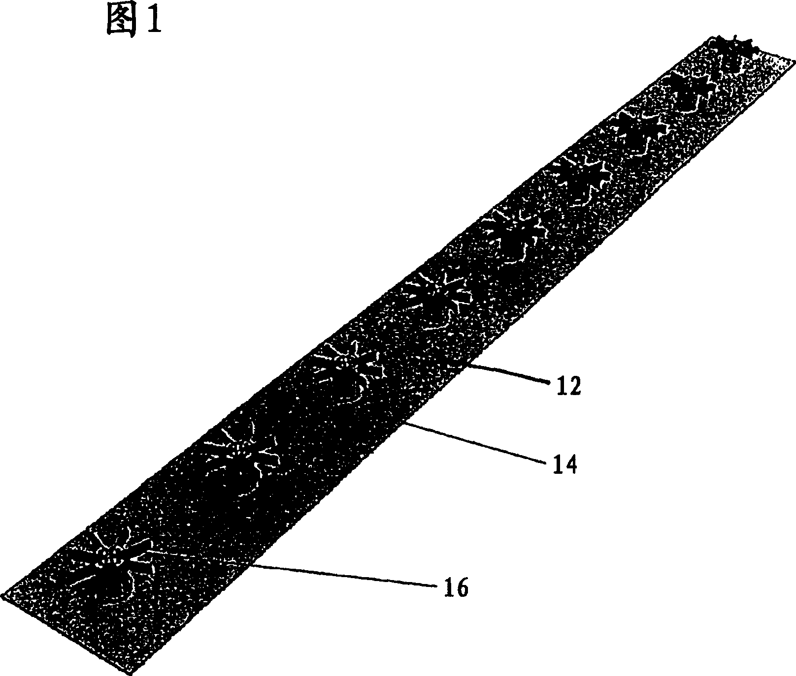
[0022] The preferred embodiment will now be described with reference to the accompanying drawings 1-6. Figure 1 shows a dual polarized antenna 14 of the present invention having a 1 x 9 dipole array 16 in accordance with the present invention. The antenna 14 includes a dipole array 16 and a reflector 12 to which the dipole array 16 is attached. Of course, it is to be understood that the present invention is not limited to a particular array.

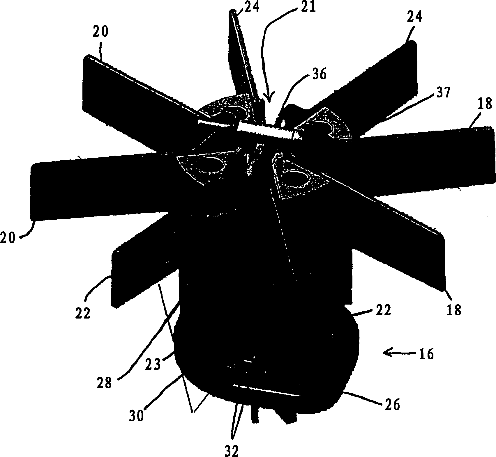
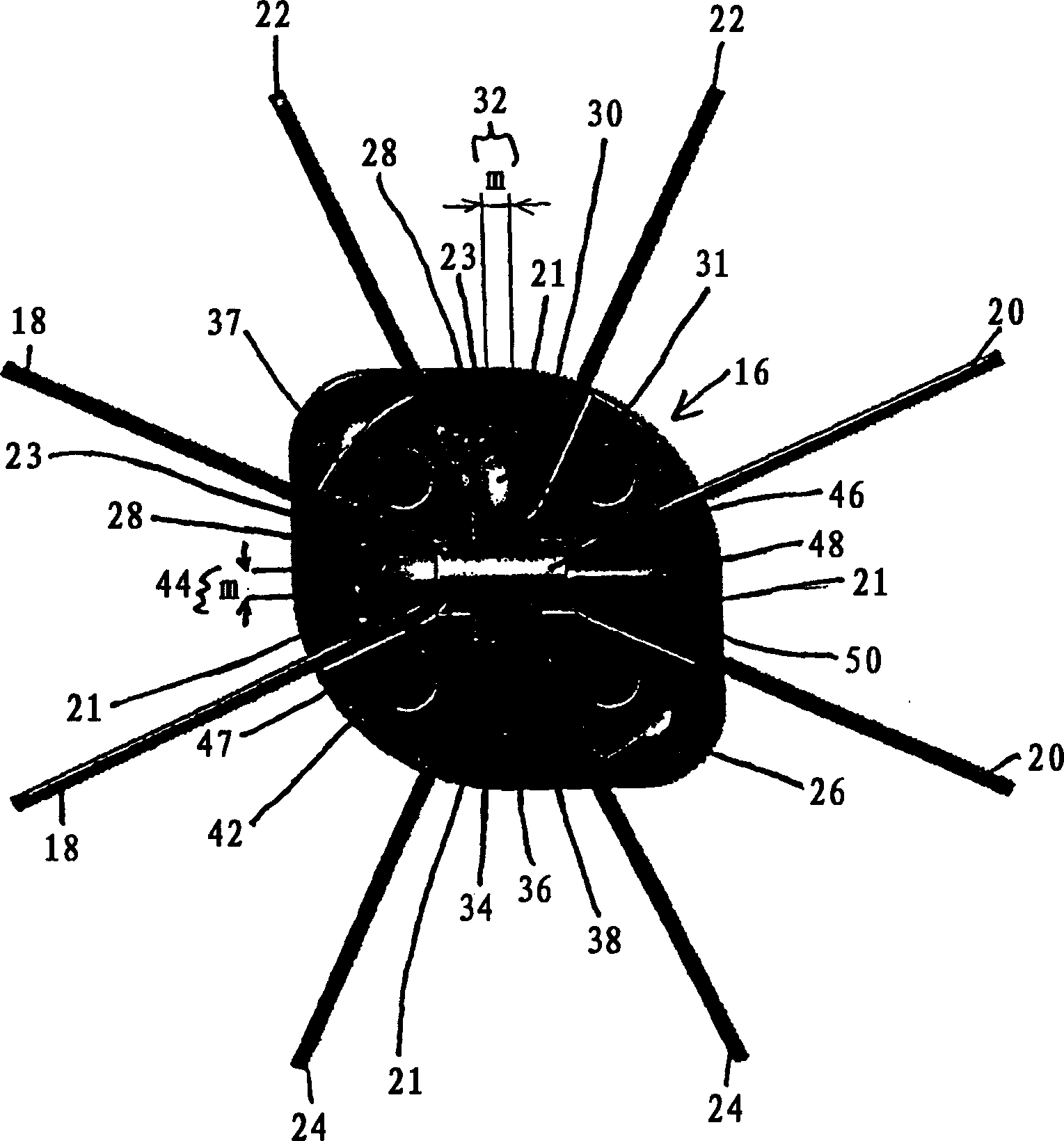
[0023] figure 2 Further details of the dipole 16 of the present invention are shown. The dipole 16 is a unitary structure comprising a base, an arm and a feed structure which will be described below. Dipoles can ...


PUM


Abstract

A polarized antenna for transmitting and receiving polarized radio frequency signals is disclosed, the antenna comprising a dipole and a dipole reflector. The dipole, including the radiating arms and the feed structure, is formed as one piece, so assembly requirements are minimal. The dipole can be formed using die machining conventional materials such as brass, aluminum and plastic, which can be plated. The feed structure through which the cables are threaded has a slotted window. The impedance of the dipole is based on the width of these windows and the size of the cable conductors. By having an integral structure, the dipole of the present invention provides ideal impedance, low intermodulation distortion, good port-to-port isolation, and good mode purity.

Description

technical field [0001] The invention relates to a double-polarized flat-panel base station antenna for a mobile communication system. More specifically, the present invention relates to dipole structures used in dual polarized panel base station antennas. Background technique [0002] Dipole antennae are very common in the communications industry. Traditional structures, such as half-wave dipoles with "bow-tie" and "butterfly" structures, are described in many books, including Banalis, Constantine A., "Antenna Theory Analysis and Design", Wiley, 1997. [0003] In particular, antennas such as flat-panel base station antennas used in mobile communication systems strongly rely on polarized antennas. In many cases, these antennas are constructed using individual linear polarizing elements combined to create dual polarization. In this case, two separate arrays of radiating elements are required to provide the two polarizations. [0004] However, it is not desirable to manufac...

Claims


Application Information

Patent Timeline
IPC IPC(8): H01Q1/24H01Q9/28H01Q9/44H01Q21/00H01Q21/06H01Q21/08H01Q21/24
CPCH01Q9/44H01Q1/246H01Q21/08H01Q21/24H01Q21/062H01Q9/28H01Q21/0087H01Q21/00
Inventor 琼-皮埃尔·哈雷尔埃里克·德布隆德戴维·科莱特尼古拉斯·科让
Owner RADIO FREQUENCY SYST
Why Eureka
Try Eureka