Auxiliary output voltage control realized using idirectional magnetization magnetic amplifier

A magnetic amplifier, auxiliary output technology, applied in control/regulation systems, output power conversion devices, DC power input conversion to DC power output, etc., can solve the problem of power converters being inflexible

Inactive Publication Date: 2003-12-17
DELTA ELECTRONICS INC
View PDF0 Cites 9 Cited by
  • Summary
  • Abstract
  • Description
  • Claims
  • Application Information

AI Technical Summary

Problems solved by technology

Therefore, the use of the power converter becomes less flexible, becaus

Method used


Image

  • Auxiliary output voltage control realized using idirectional magnetization magnetic amplifier
  • Auxiliary output voltage control realized using idirectional magnetization magnetic amplifier
  • Auxiliary output voltage control realized using idirectional magnetization magnetic amplifier

Examples


Embodiment Construction

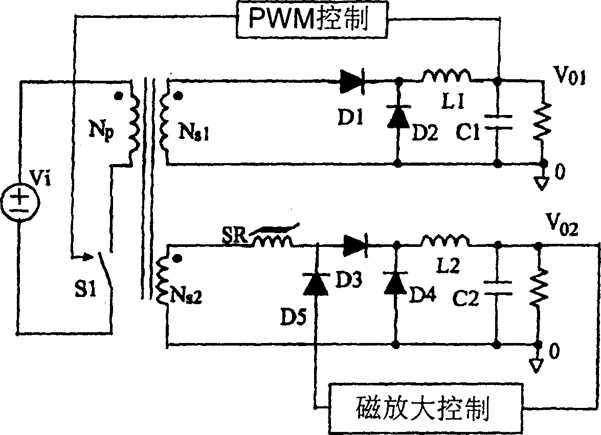
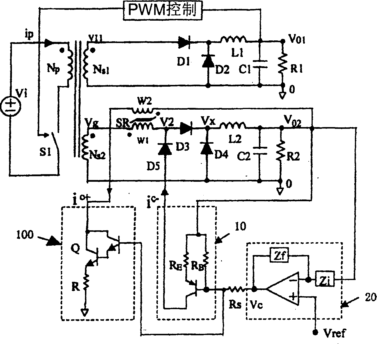
[0014] Please refer to figure 2 , The forward power converter of the present invention transfers electric energy from the primary side Np of a transformer to the secondary sides Ns1 and Ns2. The primary output voltage Vo1 and the power transferred from the first winding Ns1 are controlled by a pulse width modulation (PWM) controller, and the pulse width modulation (PWM) controller is used to switch the main switch S1 on and off. Connected with the second winding Ns2 is an auxiliary output circuit for providing the auxiliary output voltage Vo2. The auxiliary output voltage Vo2 is controlled by a magnetic amplifier including first and second induction windings W1 and W2 respectively. The induction winding W1 of the magnetic amplifier is controlled by the first control circuit 10 to realize the magnetization of the negative current ic-, and the induction winding W2 of the magnetic amplifier is controlled by the second control circuit 100 to realize the magnetization of the posi...


PUM


Abstract

An auxiliary output voltage control realized by bidirectional magnetized magnetic amplifier is disclosed. Its power transformer is composed of a transformer whose secondary side has a primary output voltage circuit and at least one auxiliary output circuit connected with magnetic amplifier, a PMW controller for controlling a switch at primary side of transformer, and a magnetic amplifier has two magnetizing windings for providing positive and negative magnetizing current.

Description

technical field [0001] The present invention relates to a configuration circuit of a switching power converter and its working method, in particular to a bidirectional magnetization control circuit of a magnetic amplifier. The control circuit is used to stabilize the auxiliary output voltage of the power converter so that the converter is The applied load range can be wider. Background technique [0002] Magnetic amplifiers are generally used to control the auxiliary output voltage of switching power converters. refer to Figure 1A , the forward power converter uses a magnetic amplifier to control the auxiliary output voltage. In a forward power converter, energy is transferred from the input voltage on the primary side, which receives power, to the secondary side, which carries the load. The transfer of energy is realized through a transformer in the form of a voltage source. The pulse width modulation (PWM) control performs the function of stabilizing the main output vo...

Claims


Application Information

Patent Timeline
IPC IPC(8): H02M1/16H02M3/335
CPCH02M1/16H02M3/33561
Inventor 陈为姜剑温兆均
Owner DELTA ELECTRONICS INC
Why Eureka
Try Eureka