Method for manufacturing piezoelectric component

A technology of piezoelectric components and manufacturing methods, which is applied in the field of piezoelectric component manufacturing, can solve the problems of long time, large frequency changes of piezoelectric filters, large frequency changes, etc.

Inactive Publication Date: 2004-01-14
MURATA MFG CO LTD
View PDF2 Cites 2 Cited by
  • Summary
  • Abstract
  • Description
  • Claims
  • Application Information

AI Technical Summary

Problems solved by technology

[0003] However, there is a problem that the frequency of the piezoelectric filter changes greatly before and after the flow of solder, and it takes a long time until the frequency returns to a stable value.
That is,

Method used


Image

  • Method for manufacturing piezoelectric component
  • Method for manufacturing piezoelectric component
  • Method for manufacturing piezoelectric component

Examples


Embodiment Construction

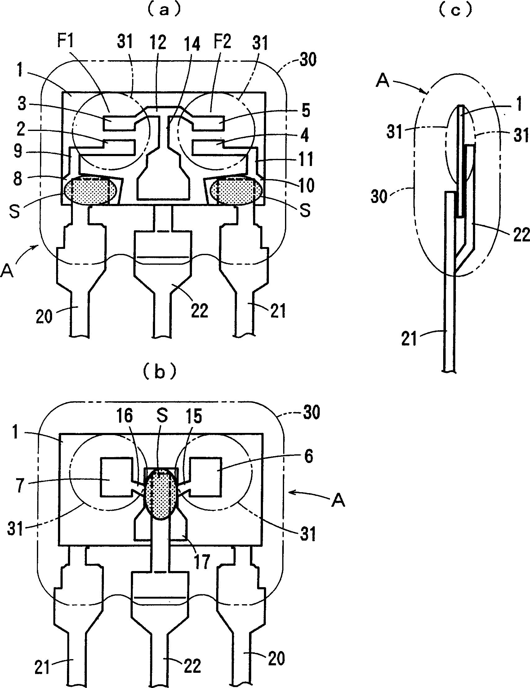
[0029] image 3 An example of a piezoelectric component manufactured by the manufacturing method of the present invention is shown. Here, an example of an energy-trapped piezoelectric filter utilizing thickness longitudinal vibration is shown.

[0030] Figure 4 is the circuit diagram of the above piezoelectric filter.

[0031] The piezoelectric filter A includes a piezoelectric element 1 made of rectangular plate-shaped piezoelectric ceramics or piezoelectric single crystal, and divided electrodes (vibration electrodes) 2, 3 and 4, 5, Counter electrodes (vibration electrodes) 6, 7 opposite to the divided electrodes 2, 3 and 4, 5 are formed in the inner main surface. Vibrating electrodes 2 , 3 , and 6 constitute one double-mode filter element F1 , and vibrating electrodes 4 , 5 , and 7 constitute the other double-mode filter element F2 .

[0032] On the outer main surface of the piezoelectric element 1, the split electrode 2 is connected to the input terminal electrode 8 fo...


PUM


Abstract

To provide a piezoelectric part manufacturing method by which a frequency change before and after soldering to a substrate is small, and by which a time can be reduced until a frequency becomes stable. A piezoelectric part manufacturing method includes a process of soldering lead terminals 20-22 to terminal electrodes of a piezoelectric element 1, a process of obtaining piezoelectric parts by spreading an armoring resin 30 around the piezoelectric element 1 in which the lead terminals are soldered and by curing the resin, a process of performing heat aging to the piezoelectric parts after curing the resin, a process of leaving the parts at room temperature until the characteristic of the piezoelectric element 1 becomes stable after the heat aging, and a process of selecting the parts by measuring the characteristic of the piezoelectric element 1 after leaving the parts at room temperature. By performing the heat aging at a stage of a completed product, a frequency change upon flow soldering at a subsequent process is made small, and a frequency is promptly made stable.(C)2004,JPO.

Description

technical field [0001] The present invention relates to a method of manufacturing a piezoelectric component such as a filter or a vibrator, and more particularly to a method of manufacturing a lead type piezoelectric component sealed with a coating resin. Background technique [0002] Heretofore, lead-type piezoelectric components sealed with a coating resin have been widely used in electronic equipment. When mounting such a piezoelectric component on a circuit board, in order to increase productivity, the lead terminals are first inserted into the circuit board by an automatic insertion machine, cut and riveted, and then soldered on the circuit board by an automatic solder bath. [0003] However, there is a problem that the frequency of the piezoelectric filter changes greatly before and after the solder flows, and it takes a long time until the frequency returns to a stable value. [0004] figure 1 Indicates the change in the frequency-attenuation characteristic of the p...

Claims


Application Information

Patent Timeline
IPC IPC(8): H03H3/02H03H9/00
CPCH10N30/875H10N30/06
Inventor 蒲生昌夫细川哲夫
Owner MURATA MFG CO LTD
Why Eureka
Try Eureka