
Connecting clamp of package board edge connector and connecting structure for package board edge connector

A technology of edge connectors and connecting fixtures, which is applied in the direction of two-part connection devices, electrical connection printed components, parts of connection devices, etc., can solve the problem that the connectors cannot be fully used effectively, achieve high reliability, prevent electronic equipment damaged effect

Inactive Publication Date: 2004-01-21
ESPEC CORP
View PDF1 Cites 1 Cited by
  • Summary
  • Abstract
  • Description
  • Claims
  • Application Information

AI Technical Summary

Problems solved by technology

However, with this configuration, there is also the problem that all the poles of the connector cannot be effectively used.

Method used


Image

  • Connecting clamp of package board edge connector and connecting structure for package board edge connector
  • Connecting clamp of package board edge connector and connecting structure for package board edge connector
  • Connecting clamp of package board edge connector and connecting structure for package board edge connector

Examples


Embodiment Construction

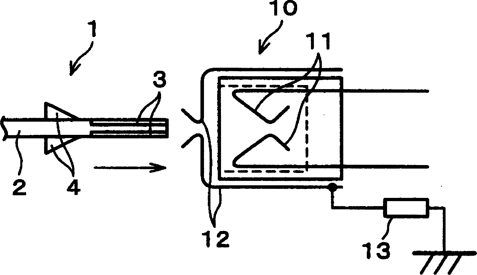
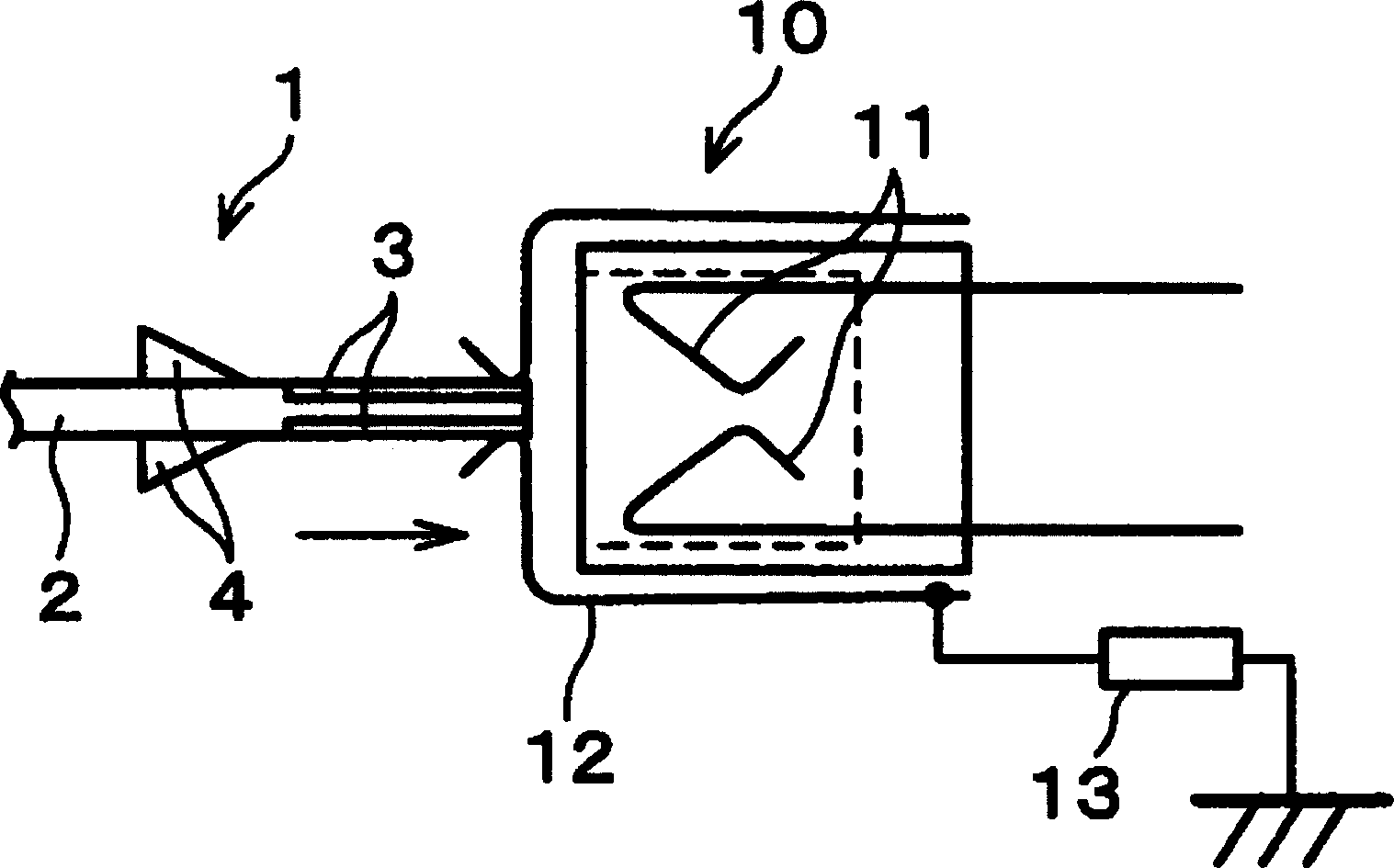
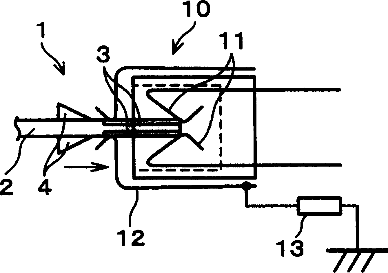
[0031] For an embodiment related to the plug-in board edge connector connection fixture and the plug-in board edge connector connection structure of the present invention, refer to Figure 1(a) ~ Figure 4(d) described as follows:

[0032] The plug-in board edge connector connection structure of this embodiment, as shown in Figure 2 and image 3 As shown, the board edge connector 10 is equipped with the electronic circuit board 1 and the short-circuit metal piece of the board edge connector connection jig.

[0033] The composition of the electronic circuit substrate 1, such as image 3 As shown, a plurality of connection terminals 3 and insulators 4 are formed on a substrate 2 . In addition, in the electronic circuit board 1 , as shown in FIG. 2 , a short circuit 5 connected to a grounding resistor 6 is connected to the wiring drawn from the connection terminal 3 .

[0034] The insulator 4 is formed on the substrate 2 to gradually increase in thickness from the connection te...


PUM


Abstract

The short circuit metal fitting 12 is made to realize such an arrangement that the distance from the contact position of the connection terminals 3 of the electronic circuit board 1 and the short circuit metal fitting 12 in the opening section of the short circuit metal fitting 12 to the contact position of the electronic circuit board 1 and the connector pin 11 of the card edge connector 10 is shorter than the length of the connection terminals 3 in a connection direction and longer than the distance from the contact position of the connector pin 11 and the connection terminals 3 to the back ends of the connection terminals 3 when the electronic circuit board 1 is completely inserted in the card edge connector 10 . On this account, it is possible to provide a card edge connector connection jig and a card edge connector connection mechanism capable of preventing breakage of an electronic device etc. due to transient current generated at the time of connection between the electronic circuit board and the card edge connector.

Description

technical field [0001] The invention relates to furniture with a plug-in board edge connector and a connection structure of the plug-in board edge connector, which can prevent electronic equipment from being damaged by transient currents (transition phenomenon currents) that occur when an electronic circuit substrate is connected to a plug-in board edge connector. Background technique [0002] In recent years, electronic equipment mounted with many electronic circuit components has been used in various fields. [0003] When assembling such electronic equipment, the electronic circuit board on which the electronic circuit components are mounted is connected to each electronic equipment or the like through a connector, and a so-called board edge connector connection is generally performed. However, in this type of board edge connector connection, when metal parts come into contact with each other during connection, a transient current (transie...

Claims


Application Information

Patent Timeline
Patent Type & Authority Applications(China)
IPC IPC(8): H01R13/652H01R13/648H05K1/11
CPCH01R12/721H01R13/6485H01R31/08H01R23/7068H01R12/71
Inventor 山本雅一
Owner ESPEC CORP
Learn More