

Sealed rectangular battery
A technology for rectangular batteries and accumulators, applied in the manufacture of airtight accumulators, alkaline accumulators, and alkaline accumulators, etc., can solve the problems of the influence of the connection part, weak strength, and increase in the internal pressure of the battery slot 52, so as to suppress the expansion and deformation. , to ensure the effect of installation strength
- Summary
- Abstract
- Description
- Claims
- Application Information
AI Technical Summary
Problems solved by technology
Method used
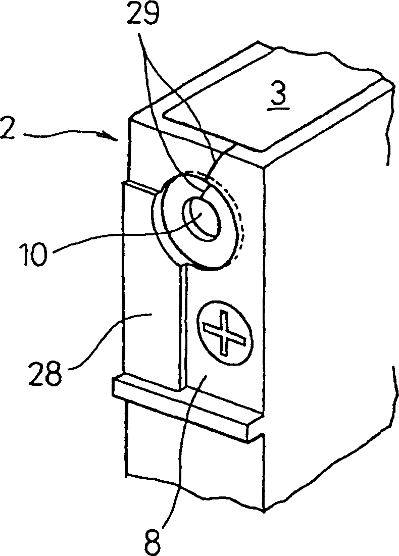
Image

Examples
Embodiment Construction
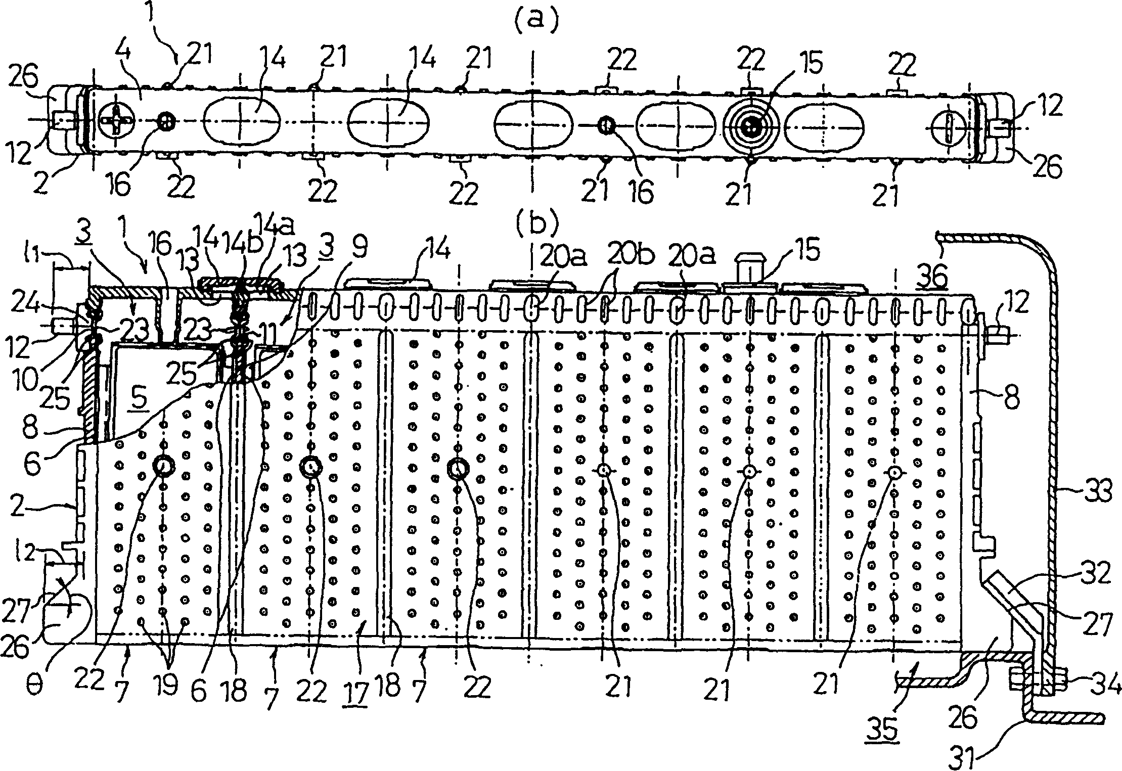
[0033] Refer to the following Figure 1-Figure 5 One embodiment of the sealed rectangular storage battery of the present invention will be described.
[0034] The sealed rectangular storage battery 1 of the present embodiment is made of a nickel-metal hydride secondary battery suitable for a driving power source of an electric vehicle, such as figure 1As shown, the short sides of a plurality of (6 in the figure) battery slots 3 in the shape of a cuboid having a narrow short side and a long long side with a long width and upper openings share a flat rectangular integrated battery slot 2 integrally connected to each other. , and the upper opening of each battery chamber 3 is integrally closed by an integral cover body 4 .
[0035] A plurality of positive plates and negative plates parallel to the long side of the battery case 3 are placed in each battery case 3, and the electrode plate group 5 stacked in the direction of the short side with an interlayer interposed therebetwee...
PUM
 Abstract
Description
Claims
Application Information