
Fastening element

A technology of fasteners and components, applied in the field of fasteners, can solve the problems of not being able to obtain permanent and reliable fixation, and achieve the effect of simplifying installation

Inactive Publication Date: 2004-01-21
THOMSON LICENSING SA
View PDF0 Cites 3 Cited by
  • Summary
  • Abstract
  • Description
  • Claims
  • Application Information

AI Technical Summary

Problems solved by technology

However, no permanent and reliable fixation can be obtained in these cases

Method used


Image

  • Fastening element
  • Fastening element
  • Fastening element

Examples


Embodiment Construction

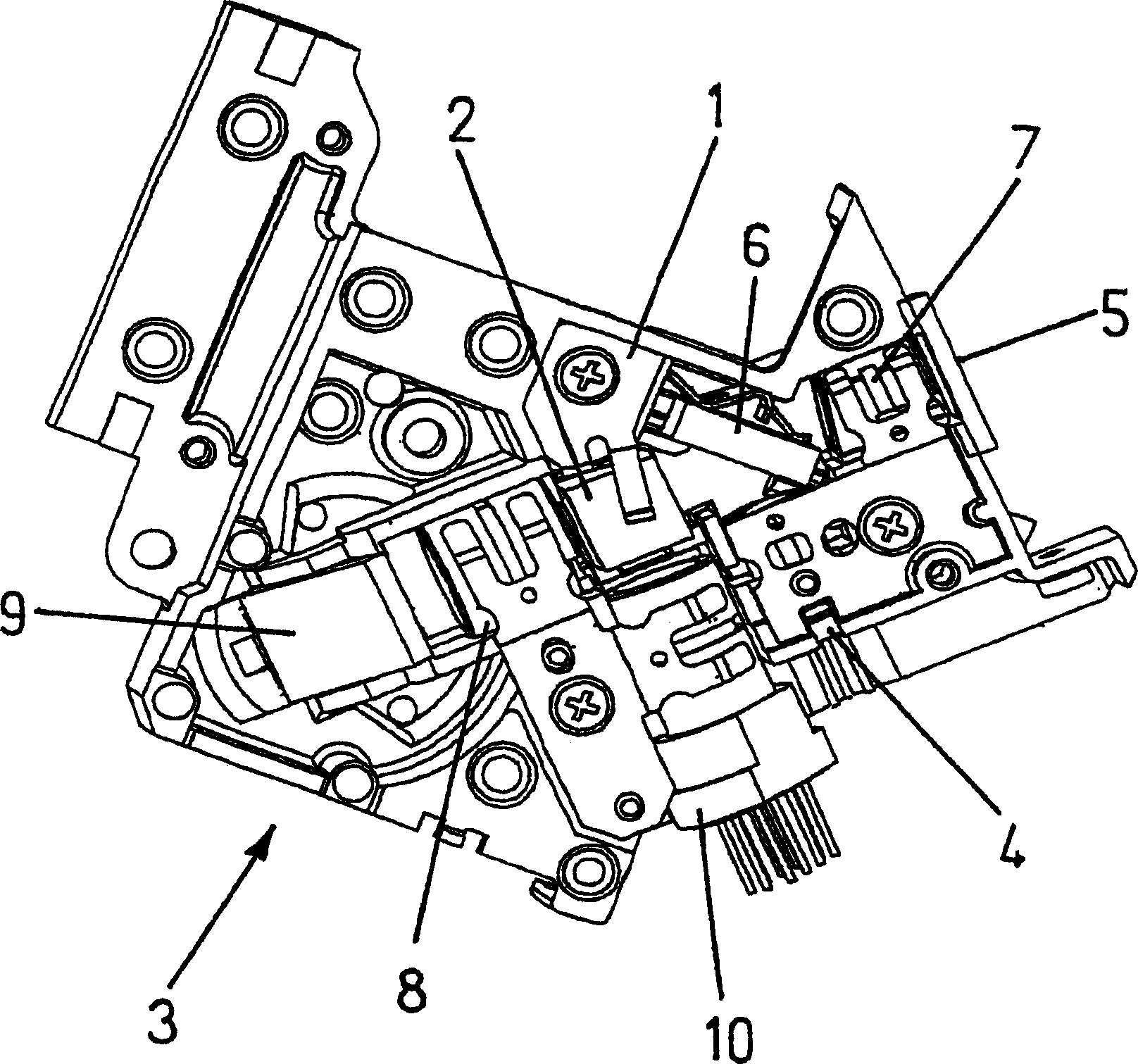
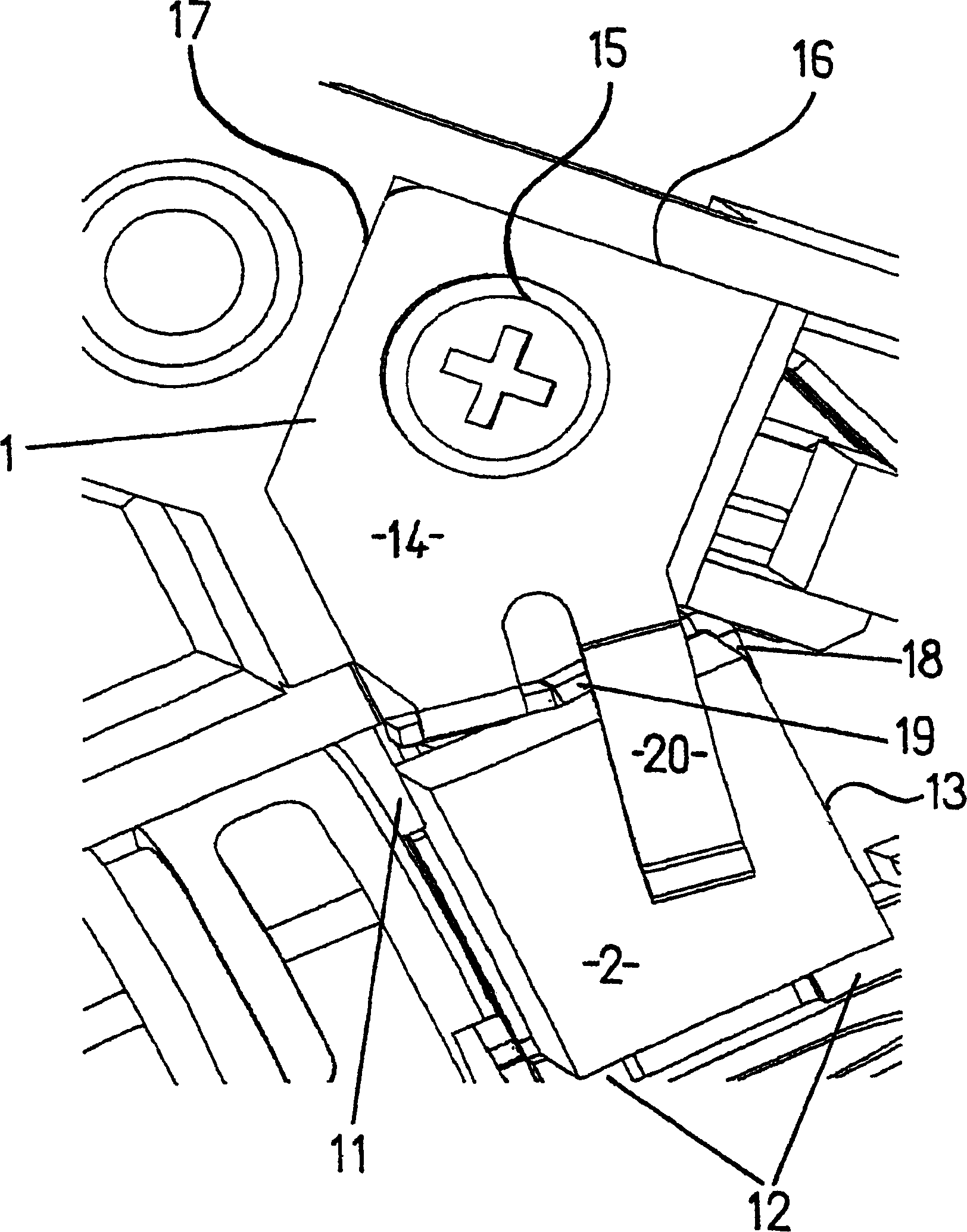
[0017] figure 1 Shown is the use of a fastener 1 according to the invention for adjusting an optical component, namely a beam splitter, in the optical path of a pickup 3 in a unit for recording information on an optical Information is reproduced on or from a recording medium.

[0018] The pickup 3 shown here is a DVD pickup, which can operate in both DVD mode and CD mode. In DVD mode, use is made by means of laser diode 4 and detector 5 . The laser beam emitted by the laser diode 4 is reflected on the half mirror 6 and passes through the beam splitter 2 . The latter is also used to reflect the return beam from the disc and deflect it to the detector 5 . In this case, the light beam passes through the half mirror 6 and is focused with the help of the lens 7 . Reference numeral 8 denotes a collimator, and 9 denotes a mirror also arranged in the optical path of the pick-up 3 . In CD mode, this use takes place by means of the holographic element 10 .

[0019] figure 2 Show...


PUM


Abstract

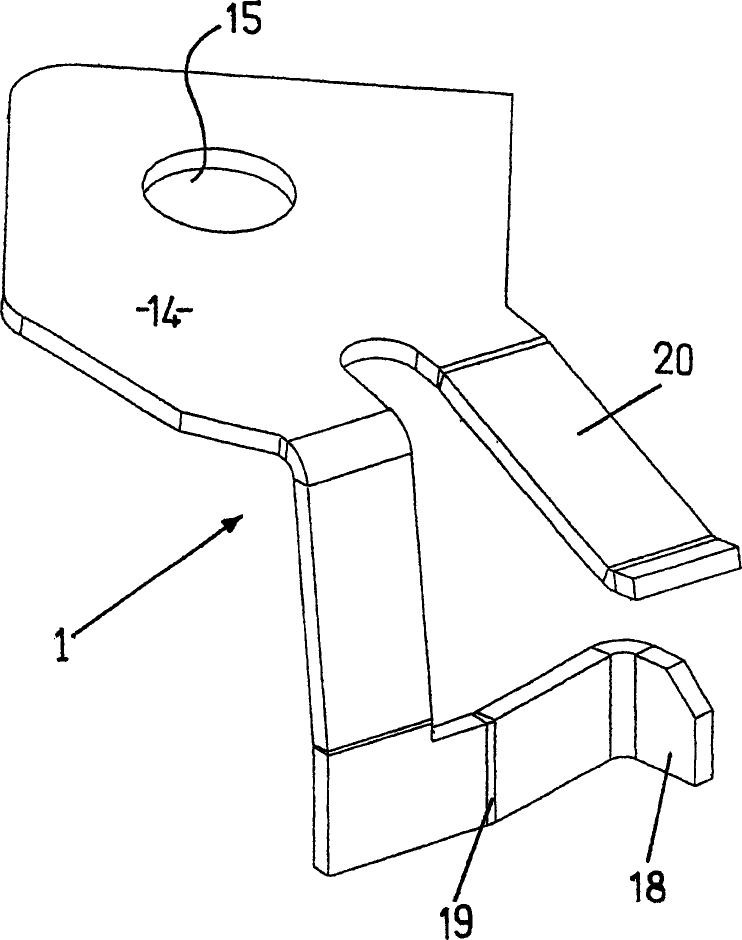
The invention specifies a possible fastening means which can be used to position components precisely, in a straightforward and permanent manner, in the body of a unit, to be precise relative to stop surfaces for the component which are formed in the unit body. This is achieved according to the invention by a fastening element (1) which has a plurality of retaining sections (18, 19, 20) which are oriented in different directions in space and via which the component (2) is pressed against the stop surfaces (11, 12) if the fastening element (1) is fixed in the envisaged position in the body of the unit (3), at least one of the retaining sections (18, 19, 20) being connected resiliently to the rest of the fastening element (1).

Description

technical field [0001] The invention relates to a fastener for adjusting a part in a unit, in the body of which a place is provided for fixing the fastener and formed for orientation in space in different directions Multiple stop faces for components. Background technique [0002] In practice, it is often necessary to position certain elements of a unit very precisely in the unit body, with the consequence that they assume a defined position relative to other parts in the unit. Examples mentioned here are the arrangement of optical components such as beam splitters, mirrors and lenses in the light path of an optical unit, e.g. the unit is used for recording information on an optical recording medium or reproduce information therefrom. [0003] In optical pickups used in CD and DVD players, for example, the beam splitter is arranged such that it allows the laser beam emitted from the laser diode to pass through, with the result that said laser beam can come into contact wit...

Claims


Application Information

Patent Timeline
Patent Type & Authority Applications(China)
IPC IPC(8): F16B2/24G11B7/12G11B7/22
CPCG11B7/22G11B7/12F16B2/245
Inventor 弗里茨·韦瑟
Owner THOMSON LICENSING SA
Learn More