Pneumatic driver with valve kinematic speed adjustment

A technology driven by air pressure and moving speed, which is applied in the direction of valve operation/release device, valve device, valve details, etc., and can solve the problems of particle generation, self damage, good rate drop, etc.

Inactive Publication Date: 2004-02-04
SILICON INTEGRATED SYSTEMS
View PDF0 Cites 0 Cited by
  • Summary
  • Abstract
  • Description
  • Claims
  • Application Information

AI Technical Summary

Problems solved by technology

The application of this pneumatic drive device often occurs that the valve itself is damaged due to too fast speed and then particles are generated, and the instantaneous pressure gradient inside and outside the valve caused by too fast valve speed, the gas convection in the reaction chamber is accelerated, and the particles attached to the inner wall of the reaction chamber are brought up.
The above situations will cause the number of particles in the reaction chamber to cause a drop in the good rate

Method used


Image

  • Pneumatic driver with valve kinematic speed adjustment
  • Pneumatic driver with valve kinematic speed adjustment
  • Pneumatic driver with valve kinematic speed adjustment

Examples


Embodiment Construction

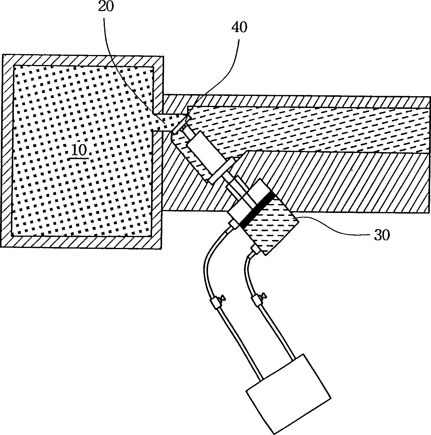
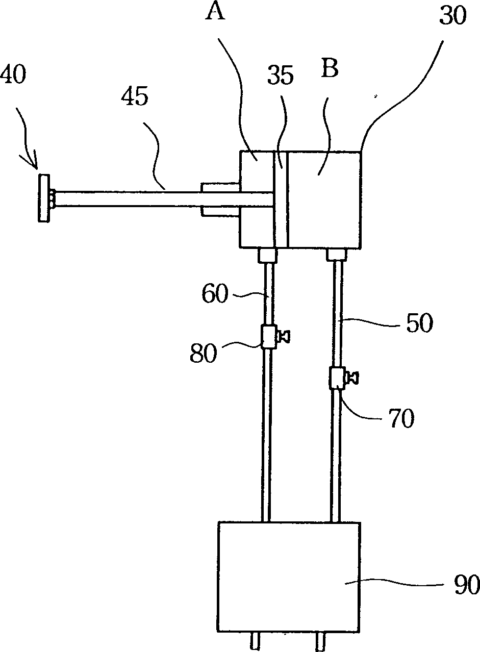
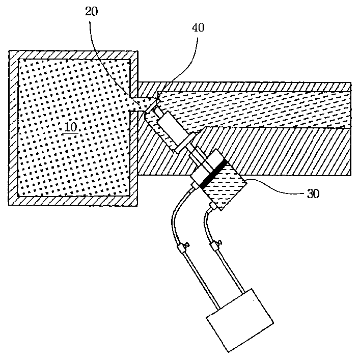
[0014] Please refer to figure 1 , which is a device diagram according to a preferred embodiment of the present invention. In the figure, the wafer port (Wafer Port) 20 of the reaction chamber (Process Chamber) 10 uses a pneumatic drive device to open and close the valve (Door) 40 . figure 2 for figure 1 An enlarged view of the pneumatic drive device. The above-mentioned pneumatic drive device includes a container body 30 in which a piston 35 is divided into a gas storage space A and a gas storage space B. The piston 35 passes through the opening of the gas storage space A through a long axis 45 Connect with valve 40. Each of the two gas containing spaces has an opening connection, the gas containing space A is connected to the gas conduit 60 , and the gas containing space B is connected to the gas conduit 50 . Both the gas conduit 50 and the gas conduit 60 are connected to a solenoid valve 90 , and a pressure regulating valve is installed between the container main body 30...


PUM


Abstract

A pneumatic driver for regulating the moving speed of valve has a main container body whose internal space is divided by a piston into two spaces with respective opening for installing tube, a pressure regulating valve installed to said tube for regulating the pressure of gas coming in said main container body, and a valve with a long axle connected to said piston via said opening. The pressure of gas in the container is regulated by said pressure regulating valve to control the speed of piston and in turn the moving speed of valve.

Description

technical field [0001] The invention relates to a pneumatic driving device for adjusting the moving speed of a valve, and is especially applied to a valve used in a semiconductor process to switch a reaction chamber. Background technique [0002] The good rate has always played an important role in semiconductor manufacturing, so semiconductor manufacturers invest a lot of manpower and money in improving and maintaining the good rate. The improvement of the good rate not only reduces the cost but also increases the profit. [0003] One of the main reasons for the decline in the good rate is the inability to effectively control the number of particles attached to the chip, because particles are one of the culprits of chip defects. Particles may damage the chip structure, leak electricity or even short circuit, making the components unusable. Because particle control is so important, semiconductor equipment will be placed in clean rooms with different cleanliness levels such...

Claims


Application Information

Patent Timeline
Patent Type & Authority Applications(China)
IPC IPC(8): F16K31/122
Inventor 陈庆任吕水烟陈明元陈意壬
Owner SILICON INTEGRATED SYSTEMS
Why Eureka
Try Eureka