Bearing projection measuring devices

A technology for measuring devices and protrusions, applied in measuring devices, mechanical measuring devices, mechanical devices, etc., can solve problems such as measurement value errors, achieve the effects of improving measurement accuracy and eliminating measurement system errors

Inactive Publication Date: 2004-02-04
ZHEJIANG UNIV
View PDF0 Cites 8 Cited by
  • Summary
  • Abstract
  • Description
  • Claims
  • Application Information

AI Technical Summary

Problems solved by technology

[0005] It can be seen from the previous error analysis that since only one instantaneous value is measured for zero measurement, the subsequent measured values ​​are all based on this ins

Method used


Image

  • Bearing projection measuring devices
  • Bearing projection measuring devices

Examples


Embodiment Construction

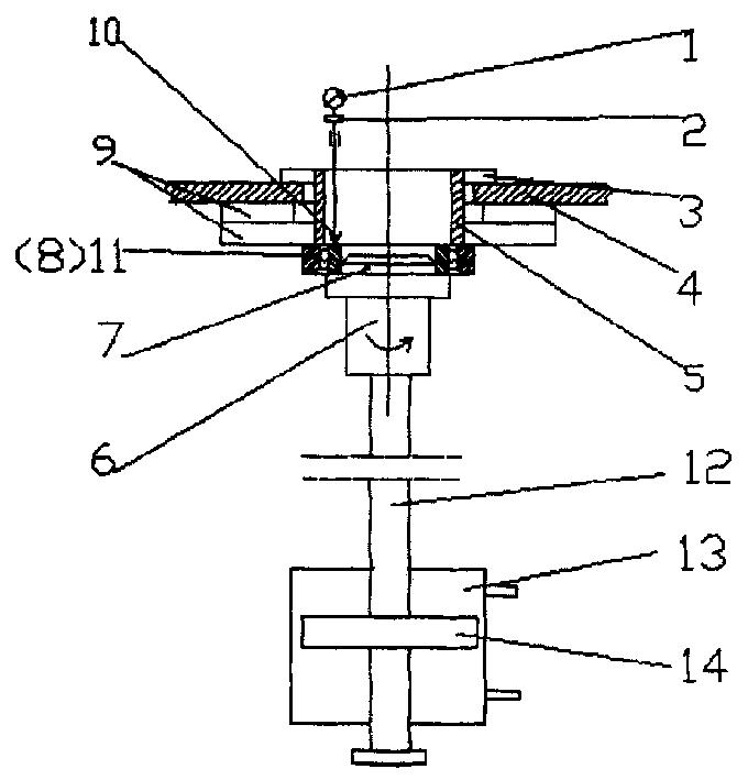
[0013] The present invention will be further described below in conjunction with the accompanying drawings and embodiments.

[0014] As shown in the accompanying drawings, the present invention consists of mechanical parts, pneumatic control parts and electrical parts. The mechanical part includes the central shaft 12 whose lower end is connected to the piston 14 installed in the cylinder 13, the upper end of the central shaft 12 is equipped with an air main shaft 6, and the upper end of the air main shaft 6 is equipped with a mandrel 7 that can match the standard ring 8 or the bearing 11 to be tested There is a central hole on the workbench 4, the lower end surface of the workbench 4 is coaxially connected with the upper ring of the air-floating thrust bearing 9, and the lower ring of the air-floating thrust bearing 9 is connected with the connecting ring 5 sleeved in the center hole of the workbench 4 The lower end is fixed, and the upper end of the connecting ring 5 is equi...


PUM


Abstract

The measuring device is composed of mechanical part, pneumatic control and electric part. The mechanical part includes centre shaft connecting down end with lifting mechanism, air mainshaft and babber matching up with standard ring or bearing to be measured. The working platform has centre hole with its down end face connected to upper ring of air floating-thrust bearing. The bearing down ring is connected to down end of connecting ring having retainer ring on it. The displacement transducer passes through inner hole of the connecting ring to contact with standard ring or end face of inner ring at bearing to be measured as its upper end is connected to electric part or indicating meter.

Description

technical field [0001] The invention relates to a metering device, in particular to a measuring device for bearing protrusion. Background technique [0002] The more advanced bearing protrusion measurement device currently in use consists of a mechanical part, a pneumatic control part and an electrical part. Among them, the mechanical part mainly includes the base, the air spindle system and the measuring and adjusting device; the pneumatic control part includes the pressurized cylinder, the compressed air pipeline, the air pressure gauge and the control valve; the electrical part includes the computer, the measuring circuit, the displacement sensor and the printer. [0003] The measurement process of this type of instrument is carried out in two steps, the first step is zero measurement: put the sensor on the center of the end face of the measuring anvil, first install the standard ring, add the measurement load, and perform static measurement to ...

Claims


Application Information

Patent Timeline
IPC IPC(8): G01B5/00
Inventor 周继烈张为民
Owner ZHEJIANG UNIV
Why Eureka
Try Eureka