Radio reception apparatus and radio reception method

A receiving device and radio technology, applied to electrical components, transmission systems, etc., can solve problems such as preventing high-precision channel estimation, deterioration of reception quality, and impossibility to obtain high-precision channel estimation

Inactive Publication Date: 2004-02-04
PANASONIC CORP
View PDF1 Cites 8 Cited by
  • Summary
  • Abstract
  • Description
  • Claims
  • Application Information

AI Technical Summary

Problems solved by technology

When the pilot signal and the simulated pilot signal are added in-phase during the repeated channel estimation process, these signals are added in equal proportions each time, therefore, the influence of errors in the simulated pilot signal has a significant effect on the number of repetitions of the channel estimation Very strong in less stages, resulting in poor reception quality
[0028] And, when the amount of phase rotation due to fading is large in the process of inserting the pilot signal, it is impossible to obtain a high-precision channel estimation value unless the influence of K slots before and after the phase change is reduced
[0029] Moreover, in the repeated channel estimation process,...

Method used


Image

  • Radio reception apparatus and radio reception method
  • Radio reception apparatus and radio reception method
  • Radio reception apparatus and radio reception method

Examples


no. 1 example

[0049] This embodiment will describe channel estimation using only pilot signals more reliable than analog pilot signals when the number of repetitions of channel estimation is 0 (hereinafter referred to as "initial stage").

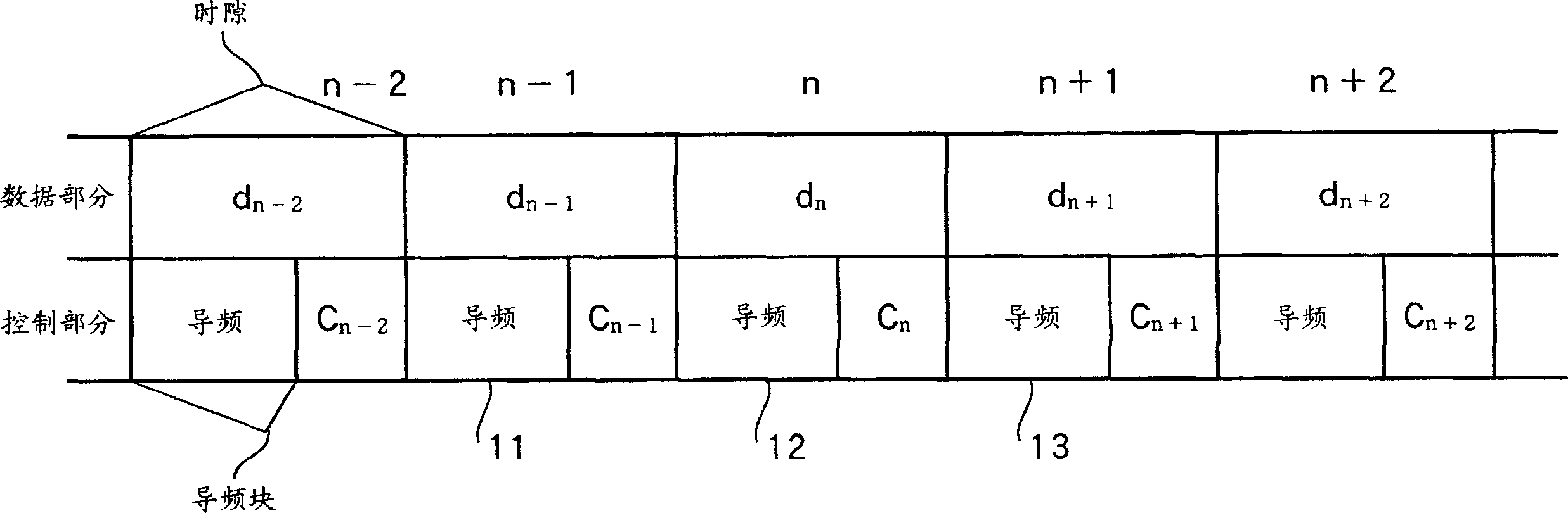
[0050] Here, the frame configuration in this embodiment is a configuration of IQ-multiplexing pilot signals and control signals of the control section and data signals of the data section. Assume that the control signal (Cn) of the control section and the data signal (dn) of the data section are taken together as signal sections (Cn, dn) other than the pilot signal.

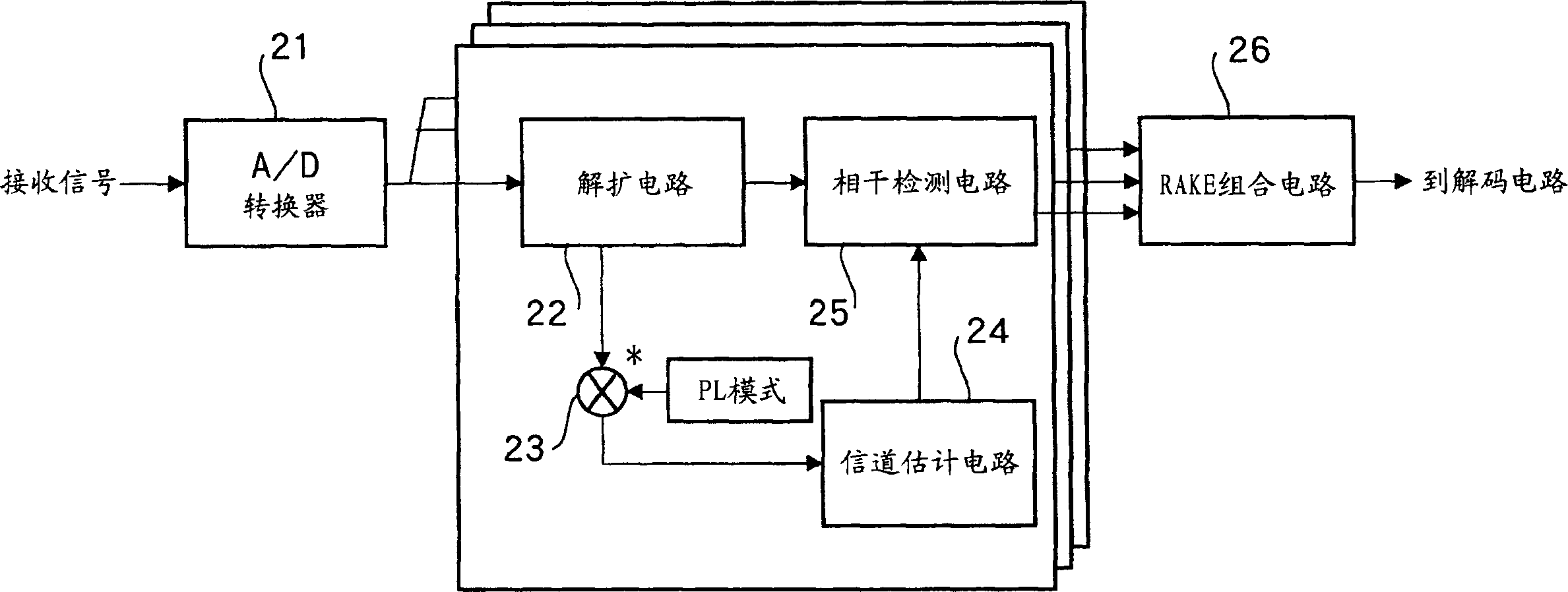
[0051] Figure 6 is a block diagram showing the configuration of the receiving device according to the first embodiment of the present invention. exist Figure 6 , each arrow is equipped with a despreading circuit 102, a multiplier 103, a channel estimation circuit 104, a coherent detection circuit 105, a multiplier 109 and a weighted addition circuit 110 ( Figure 6 An example where the...

no. 2 example

[0099] This embodiment will describe the method of making a hard decision on the demodulated signal and generating an analog pilot signal based on the result of the hard decision, in addition to using only the pilot signal for channel estimation at the initial stage as explained in the first embodiment. Condition.

[0100] Figure 8 is a block diagram showing the configuration of a receiving device according to a second embodiment of the present invention. exist Figure 8 in, with Figure 6 Those labels identical to the ones in the Figure 6 Those components that are common to the components in , and their detailed descriptions are omitted. Figure 8 and Figure 6 The difference is that in Figure 6 In, the demodulated signal from the RAKE combination circuit 106 reaches the multiplier 109 through the decoding circuit 107 and the re-encoding circuit 108, and in Figure 8 Among them, the demodulated signal from the RAKE combination circuit 106 reaches the multiplier 109 ...

no. 3 example

[0117] This example will refer to Figure 7 , Figure 10 , Figure 11 and Figure 12 , to illustrate the case where, in addition to the number of repetitions of channel estimation or CRC error detection, the weighting factor is also controlled according to the reception quality of the demodulated received signal during the weighted addition of channel estimation. exist Figure 10 , Figure 11 and Figure 12 in, with Figure 6 Those labels identical to the ones in the Figure 6 Those parts that are common to the parts in , and their detailed descriptions are omitted.

[0118] exist Figure 10 Among them, each time the channel estimation circuit 104 performs channel estimation, the repetition counter 501 counts the number of repetitions, and notifies the weighting factor control circuit 502 of the number of repetitions. In addition, when the number of repetitions reaches N, the repetition counter 501 allows the channel estimation circuit 104 to end the repeated channel ...


PUM


Abstract

When carrying out a weighted addition on the in-phase added values of pilot signals and simulated pilot signals of the data section about the nth slot, the channel estimation circuit 104 controls the weighting factors according to the number of iterations of channel estimation. That is, the channel estimation circuit (104) carries out channel estimation by decreasing weights of simulated pilot signals in addition to pilot signals in a stage in which the number of iterations is small and by increasing weights of simulated pilot signals in addition to pilot signals in a stage in which the number of iterations is large. In iterative channel estimation, this makes it possible to improve the accuracy of channel estimation in the initial stage and carry out high accuracy channel estimation with a small number of iterations of recursive channel estimation.

Description

technical field [0001] The present invention relates to a radio receiving apparatus and method for use in a digital radio communication system. Background technique [0002] (Prior Art 1) [0003] Traditionally, according to a pilot interpolation type communication system (a system that periodically inserts a pilot signal (a known signal) into an information signal), the method of using multiple pilot blocks for channel estimation was proposed by Ando et al. (RCS96-72 "Channel Estimation Scheme using Plural Pilot Blocks for DS-CDMA Mobile Radio"). Refer below figure 1 and figure 2 This channel estimation method will be described. [0004] figure 1 The time slot format used in a conventional pilot interpolation type communication system is shown. In this figure, one slot consists of a control section storing pilot signals and control signals and a data section multiplexing therewith storing data, and two slots before and after a slot n in the center are shown. time sl...

Claims


Application Information

Patent Timeline
IPC IPC(8): H04B1/707H04B1/712
CPCH04B1/7117H04B1/707H04B1/712
Inventor 桥口弘一官和行有马健晋
Owner PANASONIC CORP
Why Eureka
Try Eureka