Variable load adjustable lifting storage cabinet

A locker and adjustable technology, applied in the field of lockers, can solve problems such as unsatisfactory structure, and achieve the effects of compact structure, convenient operation and improved balance effect.

Inactive Publication Date: 2004-02-11
于维恕
View PDF6 Cites 7 Cited by
  • Summary
  • Abstract
  • Description
  • Claims
  • Application Information

AI Technical Summary

Problems solved by technology

The function of the tensioning device is only used to tension the traction cable, and cannot be used to balance the change of load, so the structure is still not ideal

Method used


Image

  • Variable load adjustable lifting storage cabinet
  • Variable load adjustable lifting storage cabinet
  • Variable load adjustable lifting storage cabinet

Examples


Embodiment Construction

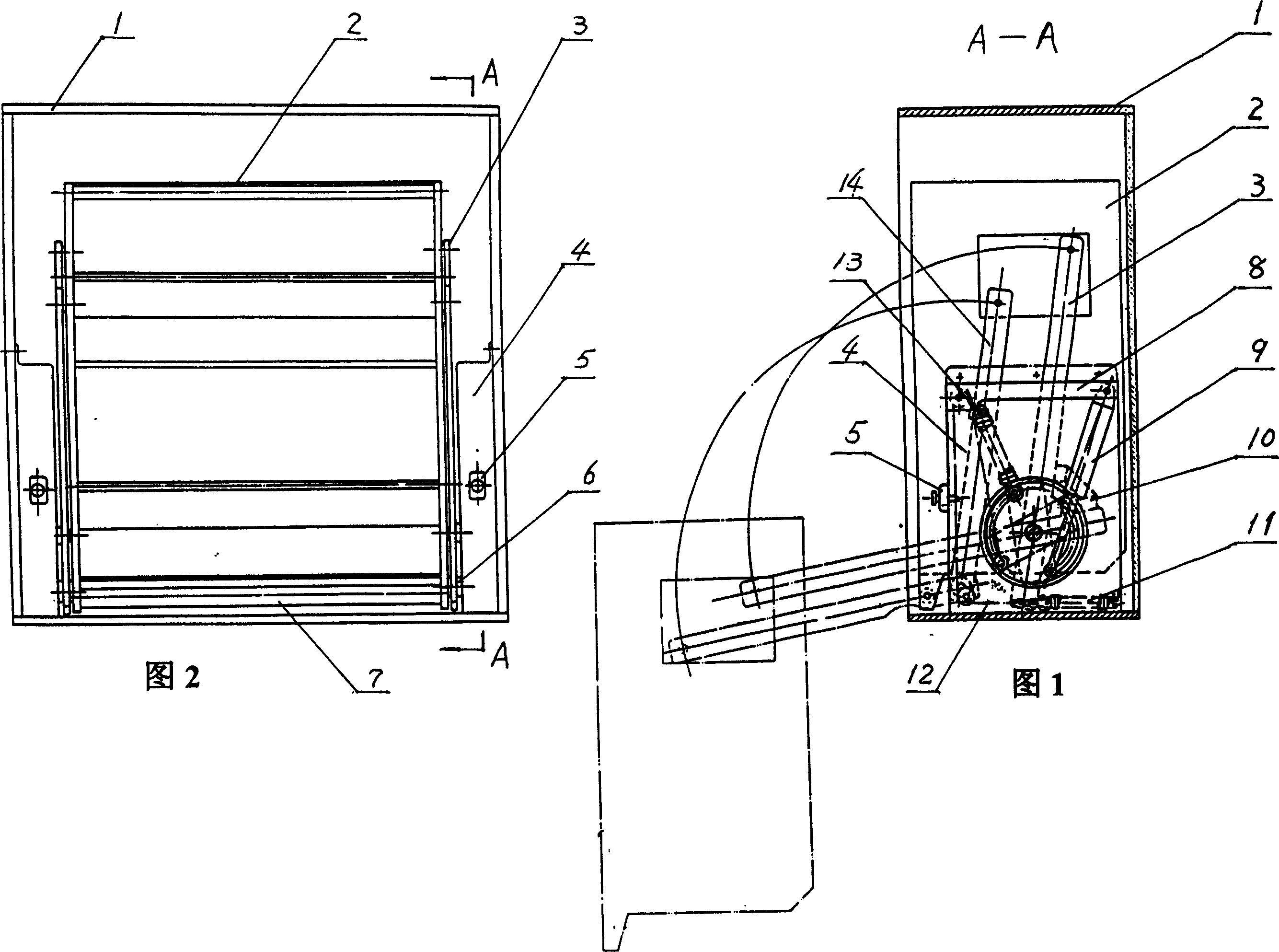
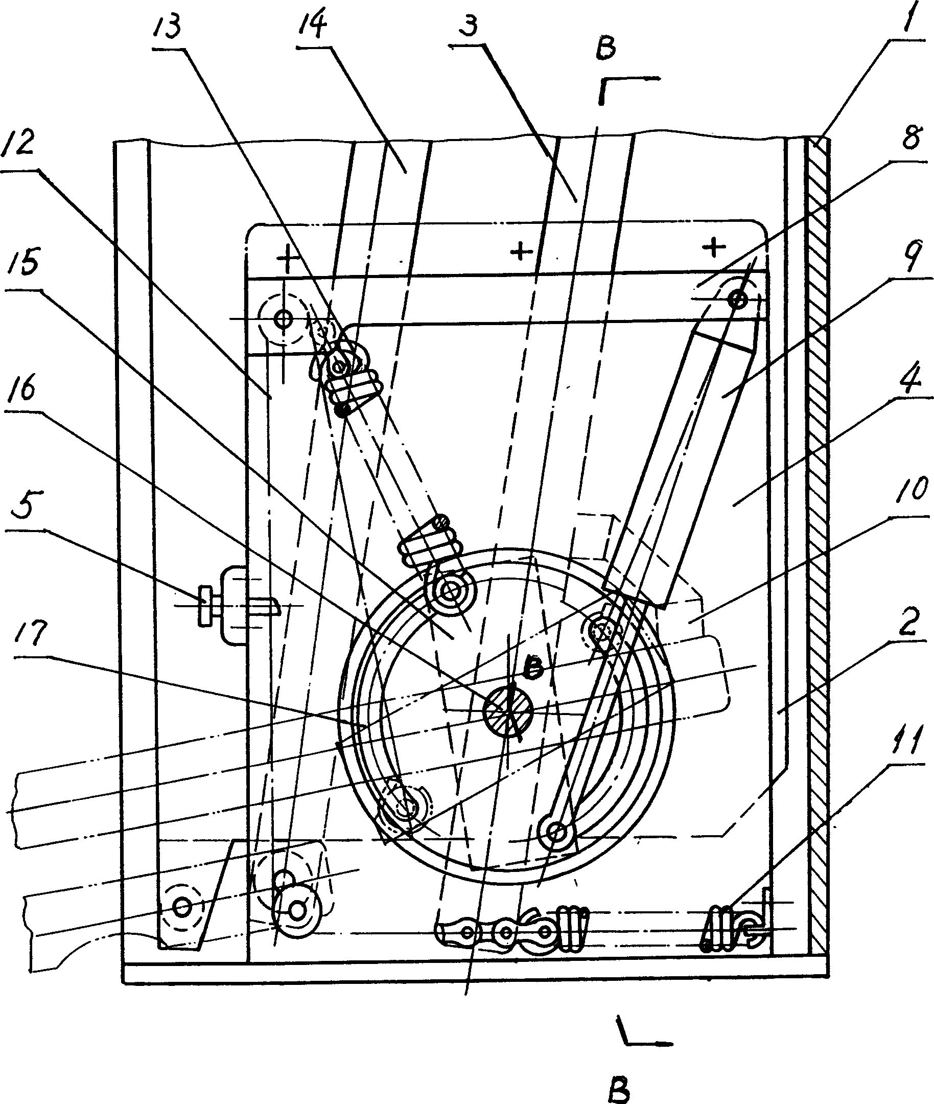
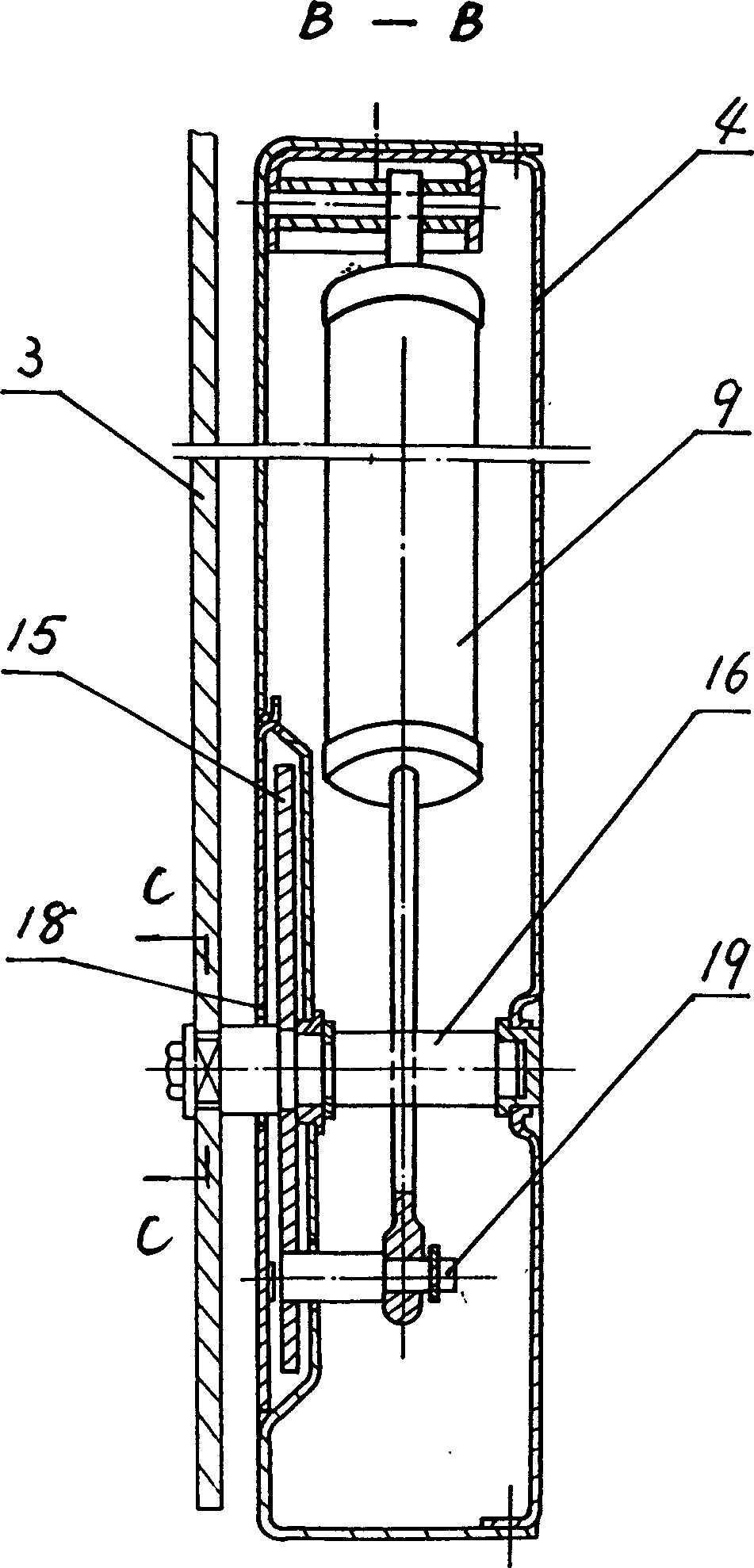
[0038] The specific structure and working process of the present invention will be described in detail according to FIGS. 1 to 21 and the embodiment. The device is improved on the basis of the basic structure of "storage rack lifting device" and "storage rack lifting and loading mechanism". It retains the original locker 1 and the storage rack 2 assembled therein and its left and right parallel linkage active linkage 3, driven linkage 14 and left and right lift controllers with energy accumulator 13 and damping buffer 9 The basic structure of other parts. Its specifications and models should be determined according to actual use requirements. The main shaft 16 fixedly connected with the active connecting rod 3 is assembled in the left and right lifting controller housing 4, and the main shaft 16 is close to the end of the active connecting rod 3, and is fixedly connected to the inside or outside of the side wall of the lifting controller housing with the shaft hole. Linkage ...


PUM


Abstract

The variable load adjustable lifting storage cabinet includes storing cabinet, storing shelf, parallel right and left linking rods and right and left lifting controller. Inside the right and left lifting controller casing, there are main shaft connected to the driving link rod, linked moving body fixed to the driving link rod, energy accumulator hinged to the casing, and damping buffer with one end hinged to the pin shaft of the linked moving body. The energy accumulator has its end hinged to the casing board connected to base spring via drawing rope; the upper end of the drawing rope has handle controlled telescopic forked pin, and the energy accumulator has rigidity greater than that of the base spring. The present invention has the features of compact structure, easy manufacture, low cost, easy operation, etc.

Description

technical field [0001] The present invention relates to a locker, especially a load-changing adjustable lift that is used in the kitchen or has a relatively high storage position and needs to be conveniently lifted and lowered, and can adapt to large load changes and can adjust the load balance along with its load-changing range. locker. Background technique [0002] At present, lockers with lifting devices generally have two structures: electric and manual. The lockers with electric structure are less used due to the limitation of use conditions; the lockers with manual structure with lifting devices are more widely used. According to foreign relevant patent document reports, JP154610 / 1986 disclosed a kind of " collection kitchen cabinet ". It uses a parallel link to directly drive a spring or an air cylinder to limit the descending speed, but the spring and the air cylinder are exposed outside without housing protection, making it unsafe to use; limited by its structure,...

Claims


Application Information

Patent Timeline
Patent Type & Authority Applications(China)
IPC IPC(8): A47B51/00
Inventor 于维恕
Owner 于维恕
Why Eureka
Try Eureka