
Switch device

A technology of switch device and group switch, which can be applied to electric switches, flip/rocker switches, switches with two operating positions, etc., and can solve the problems of complex structure and large device as a whole.

Inactive Publication Date: 2004-02-25
ALPS ALPINE CO LTD
View PDF0 Cites 4 Cited by
  • Summary
  • Abstract
  • Description
  • Claims
  • Application Information

AI Technical Summary

Problems solved by technology

However, it is necessary to consider the timing of the operation of the driving part for the push switch and the driving body 4, and it must be attached to the outside of the casing 1, so there is a problem that the entire device becomes large and the structure becomes complicated.

Method used


Image

  • Switch device
  • Switch device
  • Switch device

Examples


Embodiment Construction

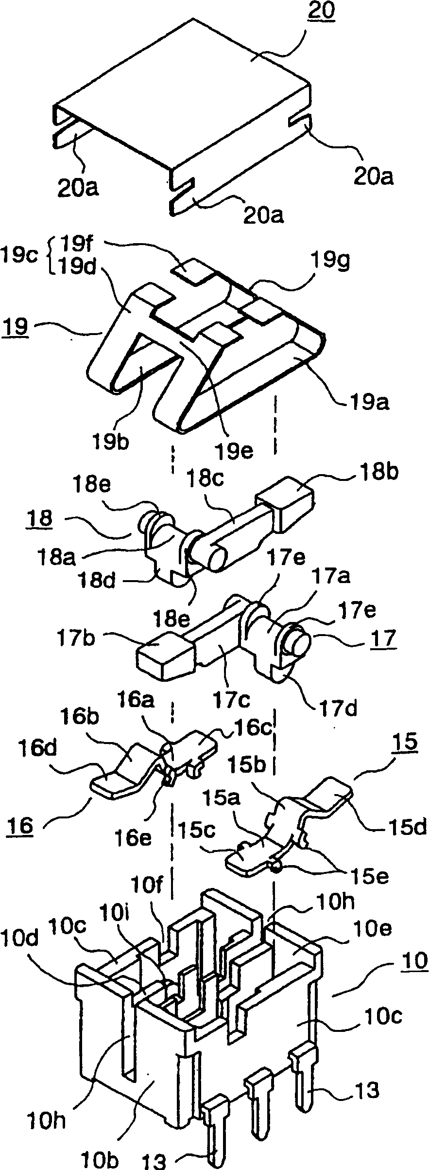
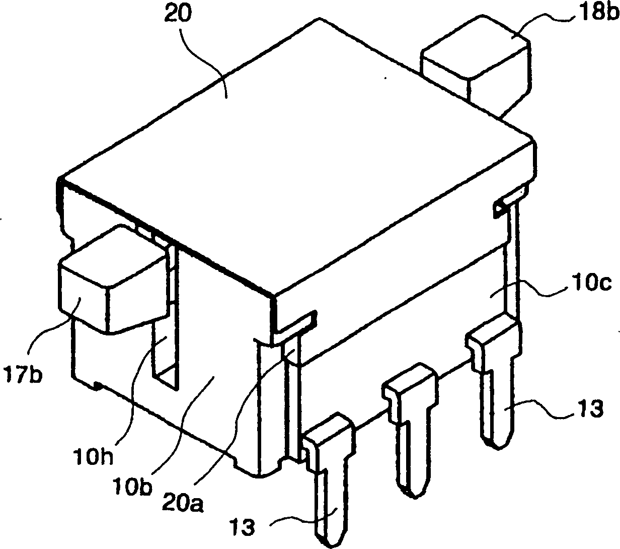
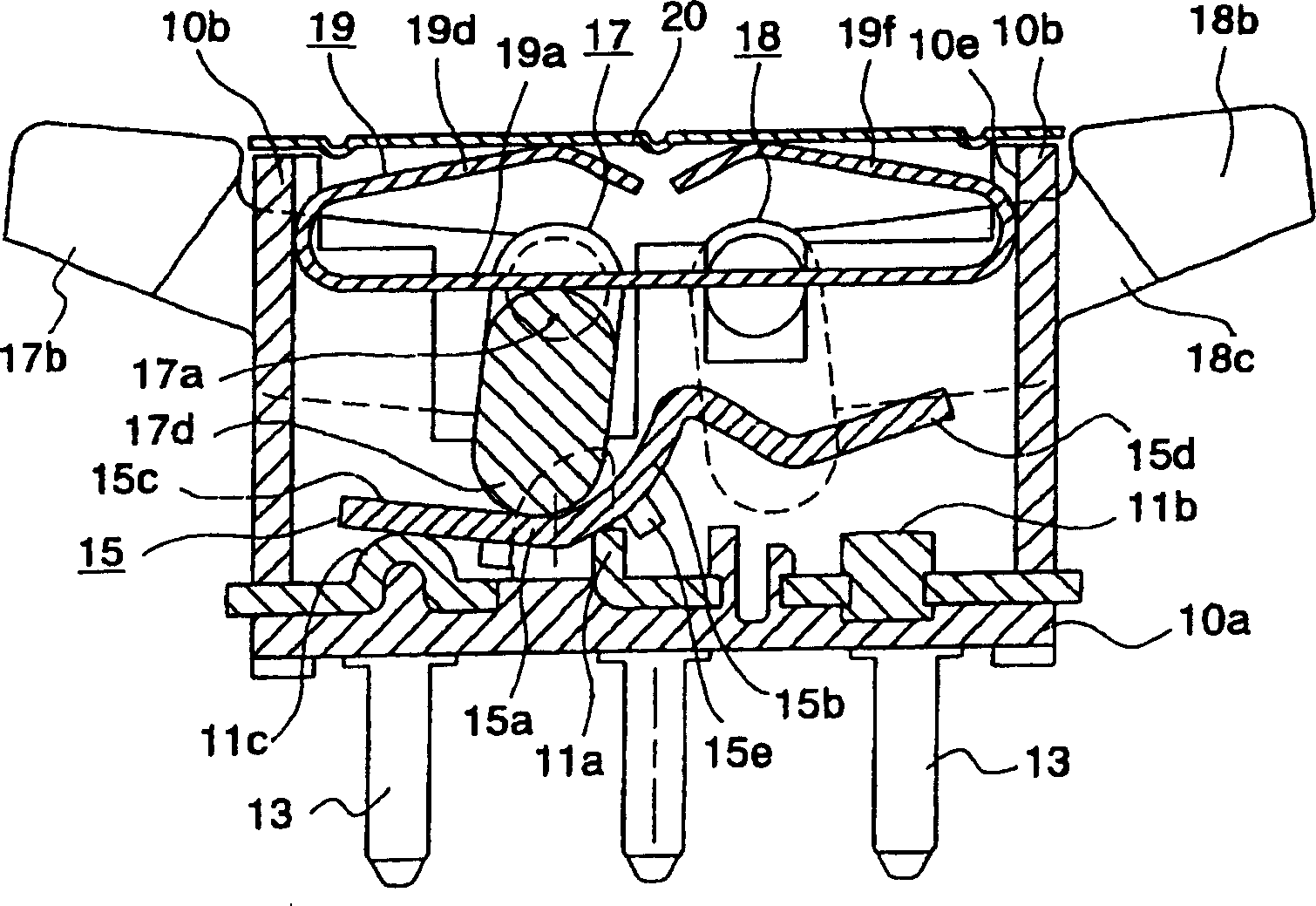
[0025] Below, with reference to accompanying drawing, embodiment of the present invention is described, figure 1 is an exploded perspective view of a switch device according to an embodiment of the present invention, figure 2 is a perspective view of the switchgear before the operation button is installed, image 3 Yes figure 2A cutaway view of the switchgear shown, Figure 4 is an explanatory diagram of the operation of the switch device, Figure 5 is a plan view of a housing included in the switch device, Image 6 is a plan view showing a state in which a conductor plate and a driver are assembled in the case, Figure 7 is expressed in Image 6 The top view of the assembled leaf spring parts in the housing shown, Figure 8 Yes Figure 7 Sectional view of the switchgear at the stage of assembly shown.

[0026] The switch devices shown in these figures are double-pole / double-throw switch devices having two sets of switching elements because they can be used as drive...


PUM


Abstract

A switch device includes two switch elements, both elements being disposed in a case and given restoring force by a common leaf spring; a cover which closes a top opening of the case; and an operating knob having two projections for selectively activating the switching elements. The leaf spring includes a compressed portion which is resiliently compressed by the cover, a pair of pressing strips which resiliently presses against each shaft of a pair of drivers of the switching elements. The operating knob presses a protruding receiver of each of the drivers, thereby selectively tilting a pair of conductive plates to output a switch ON signal.

Description

technical field [0001] The present invention relates to a switch device that is operated by rocking through an operation button, and particularly relates to switching between on and off by shaking a conductor plate to make it contact / disconnect with a fixed contact part, such as an automatic opening and closing window device for a vehicle Switching devices such as drive switches. Background technique [0002] Figure 9 It is a cross-sectional view showing a conventional example of such a switch device. As shown in this figure, first, second and third fixed contact members 2a, 2b, and 2c are fixed by insert molding to a case 1 having a bottom wall 1a. , and extend from each of the fixed contact members 2a to 2c to protrude three terminals 8 below the housing 1 . The fixed contact members 2a to 2c are exposed on the bottom wall 1a of the case 1, and the conductor plate 3 is arranged so as to be swingable with the central fixed contact member 2a as a fulcrum. The conductor pl...

Claims


Application Information

Patent Timeline
IPC IPC(8): H01H23/00H01H21/24H01H23/02H01H23/16H01H23/24
CPCH01H21/24H01H23/24H01H23/02
Inventor 佐佐木诚泽田谦次
Owner ALPS ALPINE CO LTD
Learn More