Spraying guidance system of internal combustion engine

A technology of spray guidance and internal combustion engine, which is applied in the direction of internal combustion piston engine, charging system, combustion engine, etc. It can solve the problems of short penetrating distance of umbrella-shaped spray, too thick circular distribution of mixed gas, and uneven distribution, so as to achieve fast spray dispersion speed , a large spatial range of distribution, and the effect of improving emission indicators

Inactive Publication Date: 2004-03-10
DALIAN UNIV OF TECH
View PDF0 Cites 5 Cited by
  • Summary
  • Abstract
  • Description
  • Claims
  • Application Information

AI Technical Summary

Problems solved by technology

[0003] In order to solve the problem of too thick mixed gas and uneven circumferential distribution at the landing point of the porous spray, and the short penetrating distance of the umbrella-shaped spray, the invention provides a spray guiding system for an internal combustion engine, which can provide good atomization performance, Evenly distributed in the circumferential direction, the spray will not accumulate at the landing point, but part of it will be rebounded, and the part will be quickly dispersed along the guide surface to achieve secondary atomization

Method used


Image

  • Spraying guidance system of internal combustion engine
  • Spraying guidance system of internal combustion engine
  • Spraying guidance system of internal combustion engine

Examples


Embodiment Construction

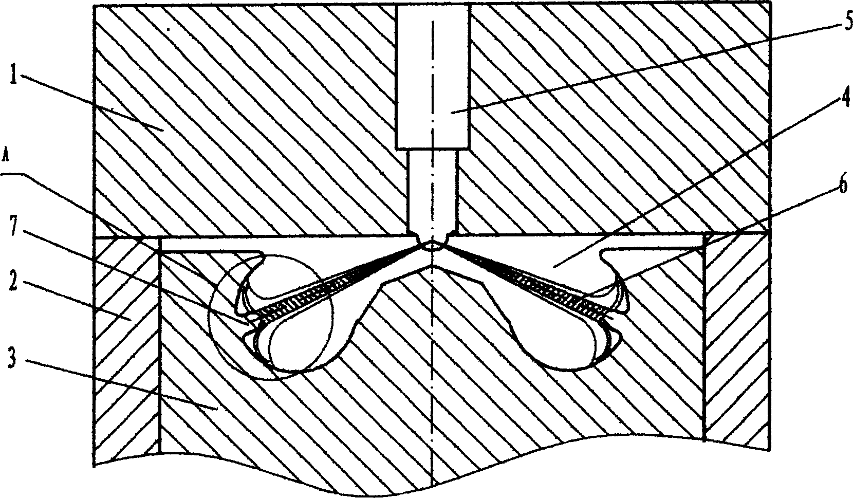
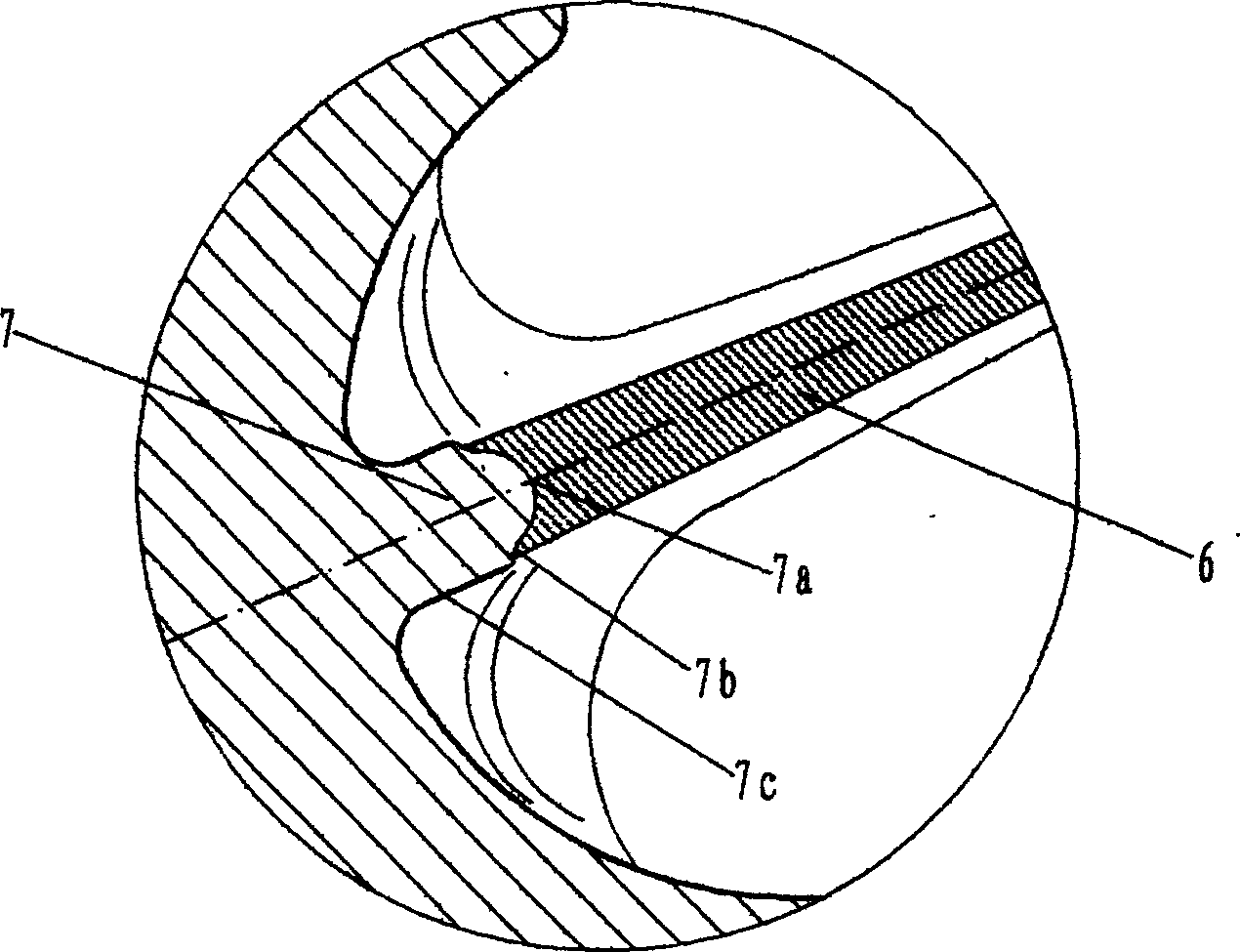
[0013] exist figure 1 , 2 In the shown embodiment, the cylinder head (1), cylinder liner (2) and piston (3) form an ω-shaped combustion chamber (4), and a cylindrical guide table (7) is provided on the inner wall of the combustion chamber (4) . The position of the cylindrical guide table (7) should ensure that in the main fuel injection stage of the engine, the oil beam (6) should be sprayed on the cylindrical guide table (7). During the upward movement of the piston, the oil beam (6) falls on the top of the guide arc (7b) and below the spherical head (7a) and the guide arc (7b) in turn, so that the spray flow can be guided to form an ideal distribution.

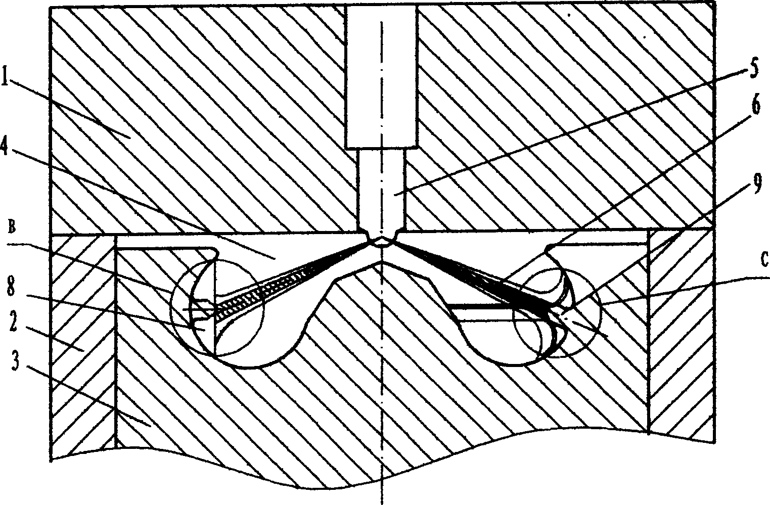
[0014] exist image 3 , 4 In the shown embodiment, the inner wall of the combustion chamber (4) is provided with a longitudinal rib-shaped guide platform (8), and during the main fuel injection stage of the engine, the oil beam (6) should be sprayed on the On the top, the oil jet (6) falls on the circular head (8a) and ...


PUM


Abstract

A spray guide system of IC engine features that a spray guide step is made on the inner surface of omega-type combustion chamber. When the pistor is raising up in the primary spray phase, the oil beam is sprayed onto said guide step, which can reflect part of the oil beam and quickly disperse the rest along its guide arc, so realizing secondary atomizing.

Description

technical field [0001] The invention relates to a spray guide system for an internal combustion engine, which belongs to the field of engine mixture gas formation and combustion. Background technique [0002] At present, the excess air coefficient of the diesel engine is relatively large, but it is easy to emit black smoke. The main reason is that the porous spray is not uniform in the circumferential direction, and an over-concentrated area is generated at the spray point. A part of the spray accumulates near the impact point or forms an oil film, and the other part rebounds and spreads to the circumference, because it is close to the wall of the combustion chamber and the amount of air involved is small. These factors constitute the main cause of carbon formation on the wall of the combustion chamber despite the large excess air coefficient of the diesel engine, but the incomplete combustion, black smoke and high hydrocarbon emissions. In order to solve this problem, alth...

Claims


Application Information

Patent Timeline
Patent Type & Authority Applications(China)
IPC IPC(8): F02M61/18
CPCY02T10/125Y02T10/12
Inventor 隆武强
Owner DALIAN UNIV OF TECH
Why Eureka
Try Eureka