Eureka AIR delivers breakthrough ideas for toughest innovation challenges, trusted by R&D personnel around the world.

Squeeze-flow combustion chamber of internal combustion engine

A technology for combustion chambers and internal combustion engines, applied to internal combustion piston engines, combustion engines, mechanical equipment, etc., can solve the problems of short penetrating distance, unevenness of umbrella-shaped spray, and too thick circular distribution of the mixed gas, so as to achieve fast spray dispersion speed, Improvement of emission indicators and the effect of a large spatial range of distribution

Inactive Publication Date: 2009-09-23
DALIAN UNIV OF TECH
View PDF4 Cites 0 Cited by
  • Summary
  • Abstract
  • Description
  • Claims
  • Application Information

AI Technical Summary

Problems solved by technology

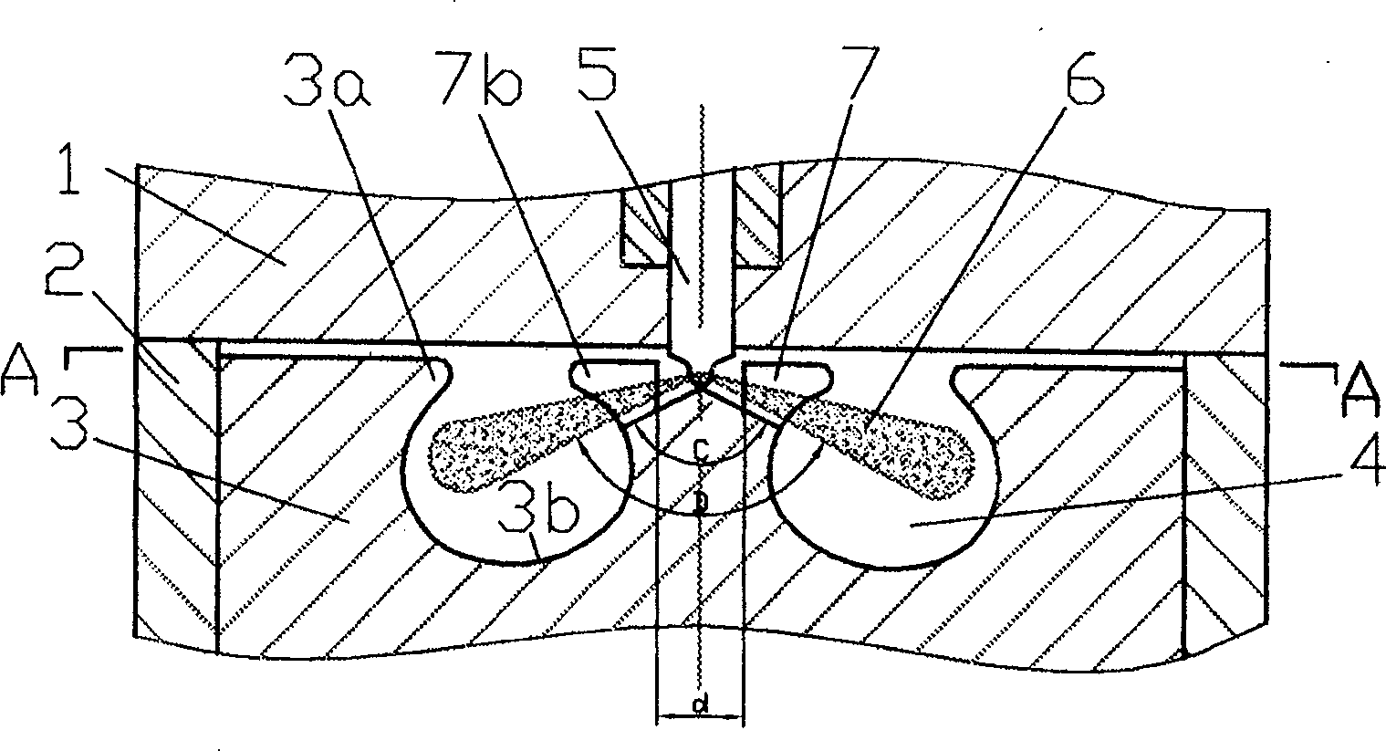
[0003] In order to solve the problems of too thick mixture and uneven distribution at the landing point of the porous spray, and the short penetrating distance of the umbrella-shaped spray, the invention provides a squish combustion chamber of an internal combustion engine, which can fully exert the squish effect, The air is concentrated in the area where the oil beam reaches, the spray space is evenly distributed, and the atomization performance is good. The spray will not accumulate at the landing point, but part of it will be rebounded, and the part will be quickly dispersed along the guide surface to achieve secondary atomization.

Method used


Image

  • Squeeze-flow combustion chamber of internal combustion engine
  • Squeeze-flow combustion chamber of internal combustion engine
  • Squeeze-flow combustion chamber of internal combustion engine

Examples


Embodiment Construction

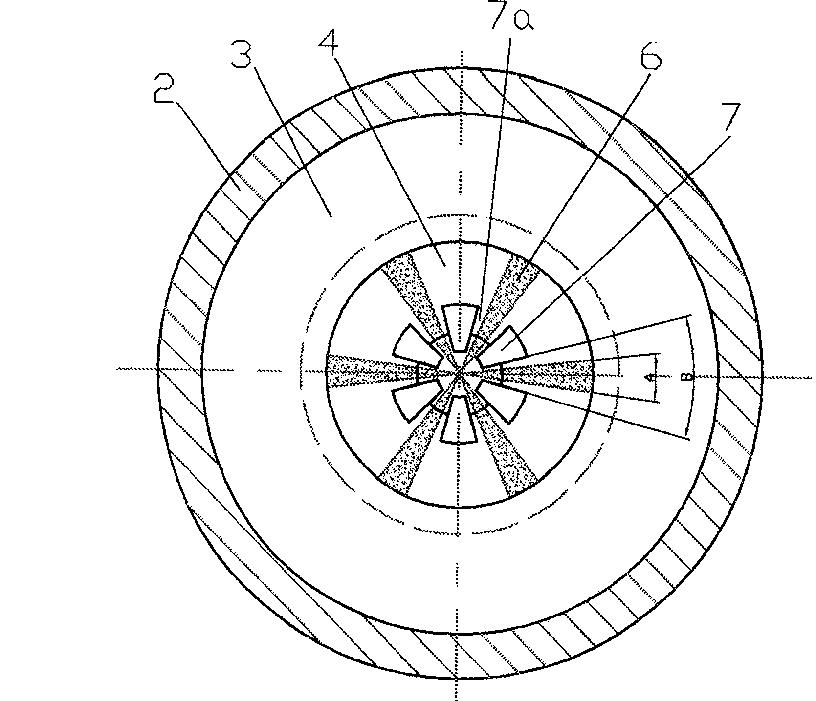
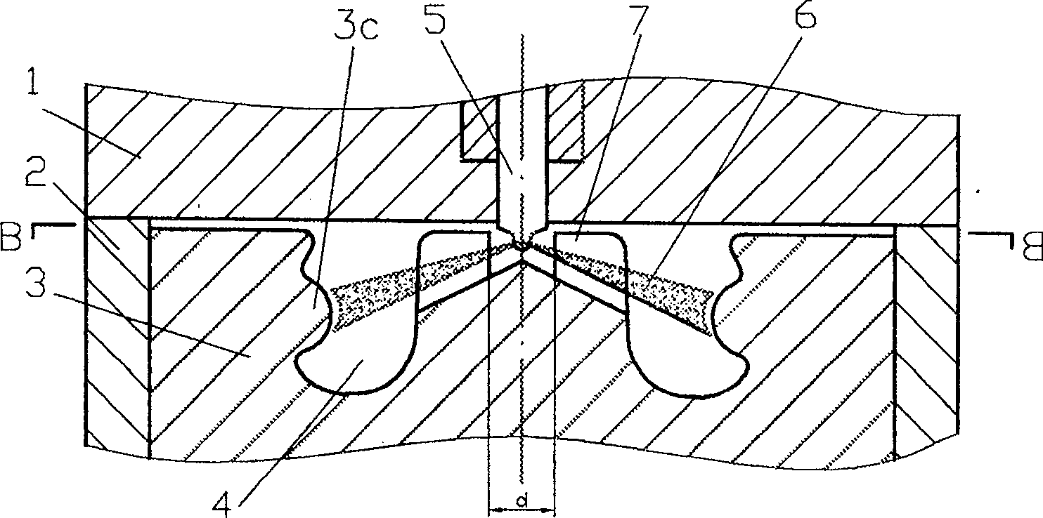
[0012] exist figure 1 , 2 In the shown embodiment, there is a combustion chamber 4 composed of a cylinder head 1, a cylinder liner 2 and a piston 3, and a squish platform 7 is arranged at the center of the piston 3, and the upper plane of the squash platform 7 is in contact with the top surface of the piston 3. flush, and there are fan-shaped grooves 7a on the squeeze platform 7, and the six oil jets 6 ejected from the fuel injector 5 just enter the combustion chamber 4 from the six fan-shaped grooves 7a. The upper part is provided with an outer closing port 3a, and the top of the squeeze platform 7 is provided with an inner closing port 7b. The two closing ports 3a, 7b and the inner wall arc 3b of the combustion chamber 4 form a mixing area where oil and gas are concentrated. In order to prevent the oil beam 6 from colliding with the wall in the fan-shaped groove 7a, it is required that the fan-shaped angle B should be greater than the atomization cone angle A of the oil bea...


PUM


Abstract

The present invention is flow-extruding combustor for internal combustion engine and belongs to the field of the formation and combustion of mixed gas in internal combustion engine. The flow-extruding stage set inside the combustor concentrates air inside the combustor to the area the sprayed oil beam can reach easily, and the collision stage makes the oil beam develop along the guide arc without deposition in the falling point in high dispersion speed, large distribution space range separated from the combustor and increased involved air amount, so as to form homogeneous mixed gas fast, improve the quality of the inflammable gas mixture in engine and perfect the combustion without needing great air eddy current. The present invention can improve obviously the fume exhaust index of internal combustion engine and raise the kinetic and economic indexes.

Description

technical field [0001] The invention relates to a squish flow combustion chamber of an internal combustion engine, which belongs to the field of engine mixture gas formation and combustion. Background technique [0002] At present, the excess air coefficient of the diesel engine is relatively large but it is easy to emit black smoke. The main reason is that the porous spray is not uniform in the circumferential direction. There is only air in the center of the combustion chamber and there is very little fuel. thick area. A part of the spray accumulates near the impact point or forms an oil film, and the other part rebounds and diffuses in the circumferential direction, so that the amount of air entrained close to the wall of the combustion chamber is small. These factors constitute the main cause of carbon formation on the wall of the combustion chamber despite the large excess air coefficient of the diesel engine, but the incomplete combustion, black smoke and high hydroca...

Claims


Application Information

Patent Timeline
Patent Type & Authority Patents(China)
IPC IPC(8): F02B23/00F02F3/26
CPCY02T10/125Y02T10/12
Inventor 隆武强杜宝国田华
Owner DALIAN UNIV OF TECH
Why Eureka
Eureka Blog
Learn More