

Laterally floating latch hub assembly
A lock and component technology, applied to building locks, connecting components, electrical components, etc.
- Summary
- Abstract
- Description
- Claims
- Application Information
AI Technical Summary
Problems solved by technology
Method used
Image

Examples
Embodiment Construction
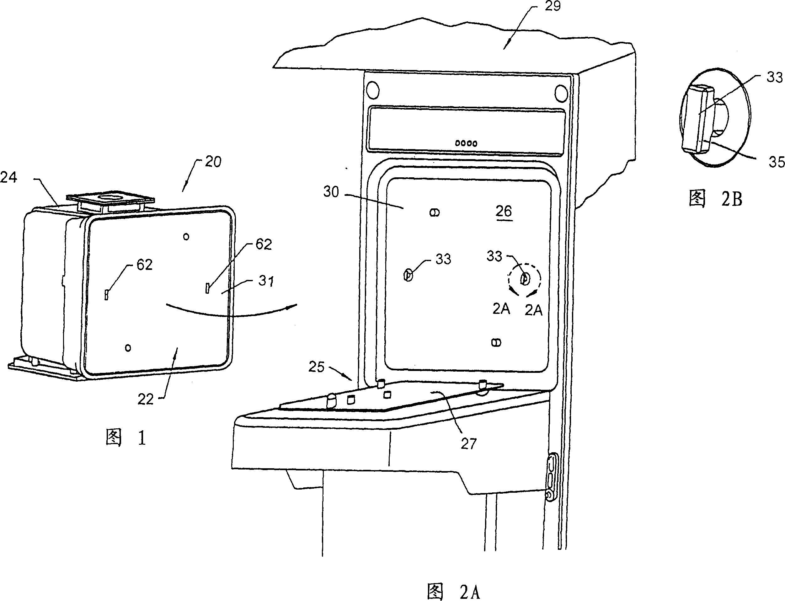
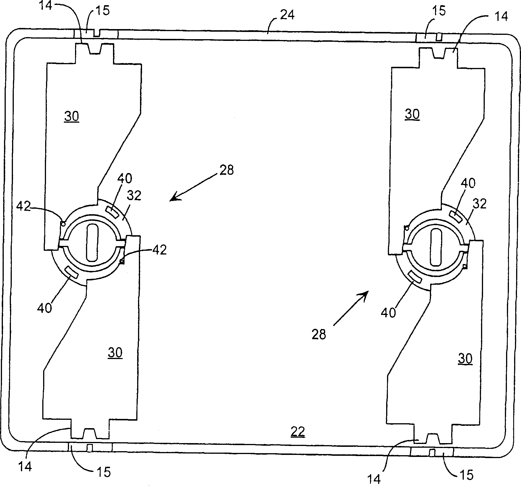
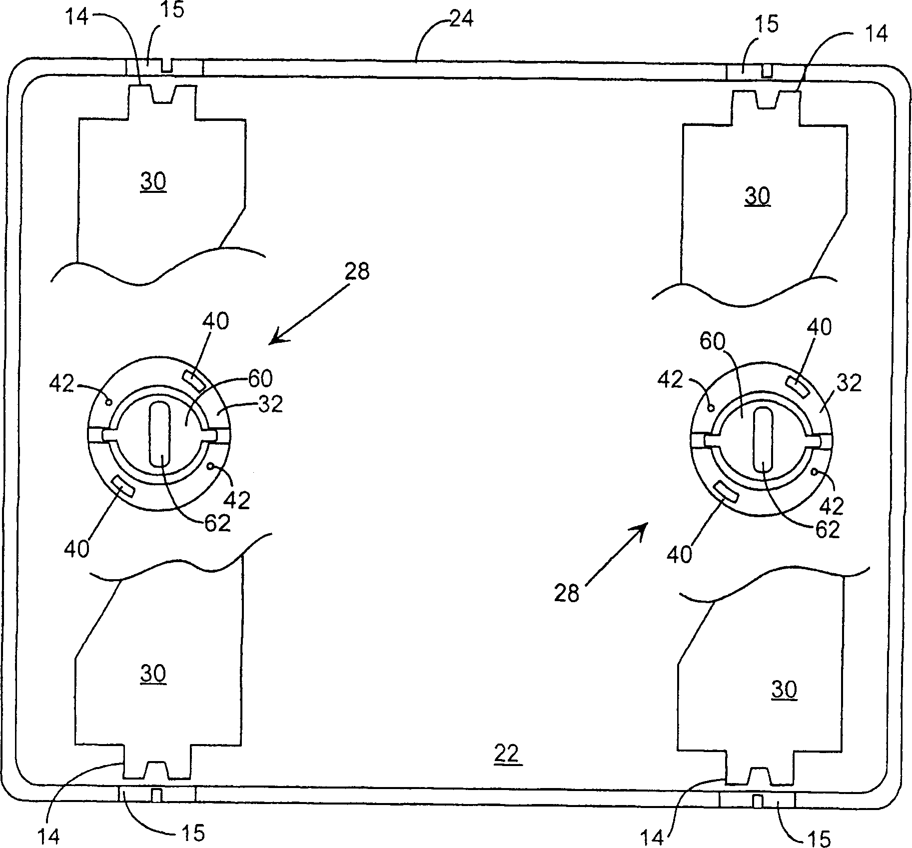
[0040]The present invention will be described in detail with reference to Figures 1-15, wherein the preferred embodiment relates to a FOUP door which includes a laterally floating snap lock cylinder assembly. In a preferred embodiment, laterally floating snap lock cylinder assemblies are combined with other conventional snap lock cylinder assemblies for use in a FOUP with or without a FOUP door.
[0041] Referring now to FIG. 1 , there is shown a perspective view of a 300mm FOUP 20 including a FOUP door 22 mated to a FOUP housing 24 so that one or more workpieces located therein form a closed environment. (When the FOUP is on the aisle, the rear of the container door 20 generally faces the aisle door. For clarity, it is shown otherwise in FIG. 1.) When the container door 20 is a 300mm FOUP, the size and type of container does not The invention is not limited. To transfer workpieces between FOUP 20 and process tool 29 (FIG. 2A), the FOUP is loaded at load port 25 adjacent acce...
PUM
 Abstract
Description
Claims
Application Information