Vacuum circuit-breaker and a method for controlling the same

A technology of vacuum switch and control system, applied in the field of control system, can solve the problems of high technical cost and the like

Inactive Publication Date: 2004-03-31
SIEMENS AG
View PDF1 Cites 1 Cited by
  • Summary
  • Abstract
  • Description
  • Claims
  • Application Information

AI Technical Summary

Problems solved by technology

Outside of this zone of elimination, it is technically expensive to

Method used


Image

  • Vacuum circuit-breaker and a method for controlling the same
  • Vacuum circuit-breaker and a method for controlling the same
  • Vacuum circuit-breaker and a method for controlling the same

Examples


Embodiment Construction

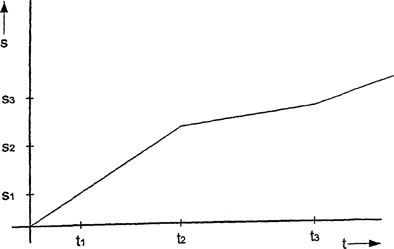
[0032] figure 1 , 2 and 3 show the path-time diagrams of the opening movement of the vacuum switch. Recorded on the abscissa of the coordinate system is the elapsed time t during a disconnection process in which the electrical separation of the contact parts begins at the origin of the coordinates. Recorded on the vertical axis is the mutual distance s of the contact parts. figure 1 Shows a possible course of a breaking movement according to the invention. At the point in time t=0 the disconnection movement starts. The contact parts are electrically separated. The distance between the two contact parts is first continuously increased. A first contact point distance s1 of the contact portion is reached at a first point in time t1. The separation of the contact parts takes place at a constant speed until the second point in time t2. At a second point in time t2 a second contact point distance s2 is reached. After the second contact point distance s2 has been reached, the...


PUM


Abstract

The aim of the invention is to improve the interrupting capacity of a vacuum switch, to achieve this, the contact parts (4, 5) that can be displaced in relation to each other are separated at a variable speed. Separation takes place in such a way that during a predetermined time period a predetermined distance between the contacts is not exceeded. To prevent said predetermined distance from being exceeded, a braking element is allocated to the vacuum circuit breaker.

Description

technical field [0001] The invention relates to a control system for controlling a vacuum switch, the contact point system of which comprises at least two relatively movable contact parts, which are separated from each other at a variable speed during an opening process, and between which A light arc to be eliminated is burned during this disconnection process. Background technique [0002] Such a control system is known, for example, from patent document DE 3815805 C2. The opening movement of a contact point arrangement of a vacuum switch is controlled by an eccentric drive. Here, the configuration of the mechanical actuation chain was chosen such that after a very short acceleration phase (1.3 ms) of a displaceable contact part, an open path of 1 mm of the contact part was achieved. Furthermore, it is stated that it proves to be particularly advantageous if the contact point separation speed reaches 2 m / s after 0.8 ms. This technical solution is based on the considerati...

Claims


Application Information

Patent Timeline
IPC IPC(8): H01H33/66H01H33/664H01H33/666
CPCH01H33/664H01H33/666H01H2009/307
Inventor 伯恩德-海科·克拉夫特卡尔·马施尔
Owner SIEMENS AG
Why Eureka
Try Eureka