Oscillating current assisted spin torque magnetic memory

a technology of assisted spin torque and magnetic memory, which is applied in the direction of oscillator generators, digital storage, instruments, etc., can solve the problems of reducing the stability of magnetic elements, excessive heat generation, and small size, and achieves the effect of reducing the switching current and improving the switching performance of the memory cell

Inactive Publication Date: 2010-09-21
SEAGATE TECH LLC
View PDF13 Cites 26 Cited by
  • Summary
  • Abstract
  • Description
  • Claims
  • Application Information

AI Technical Summary

Benefits of technology

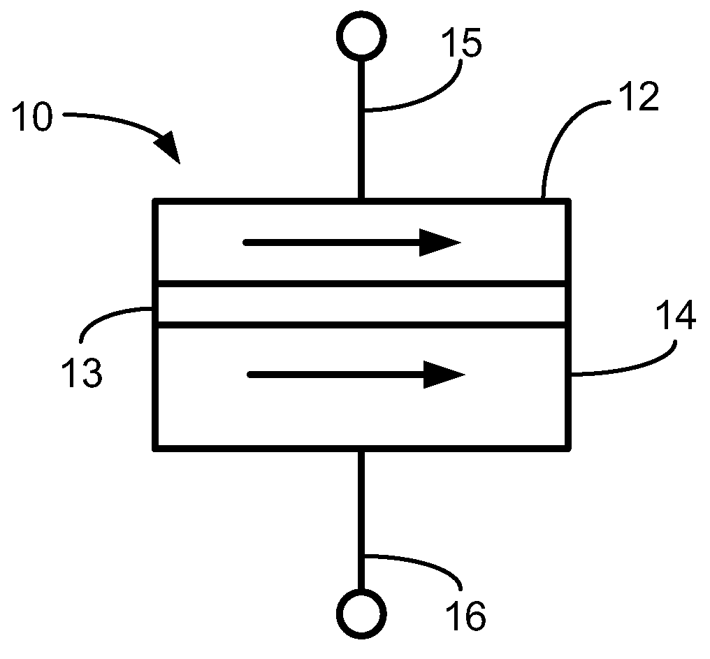
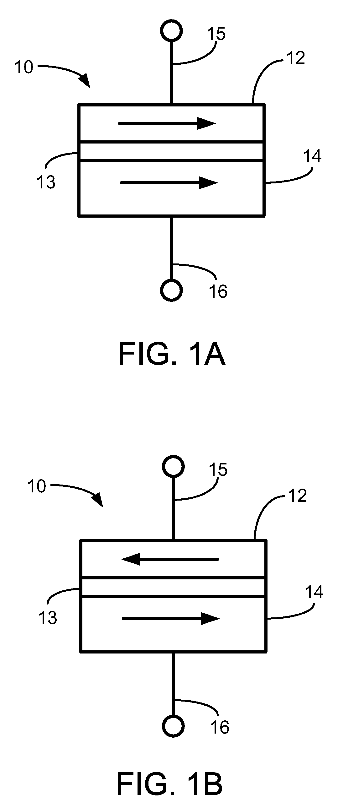
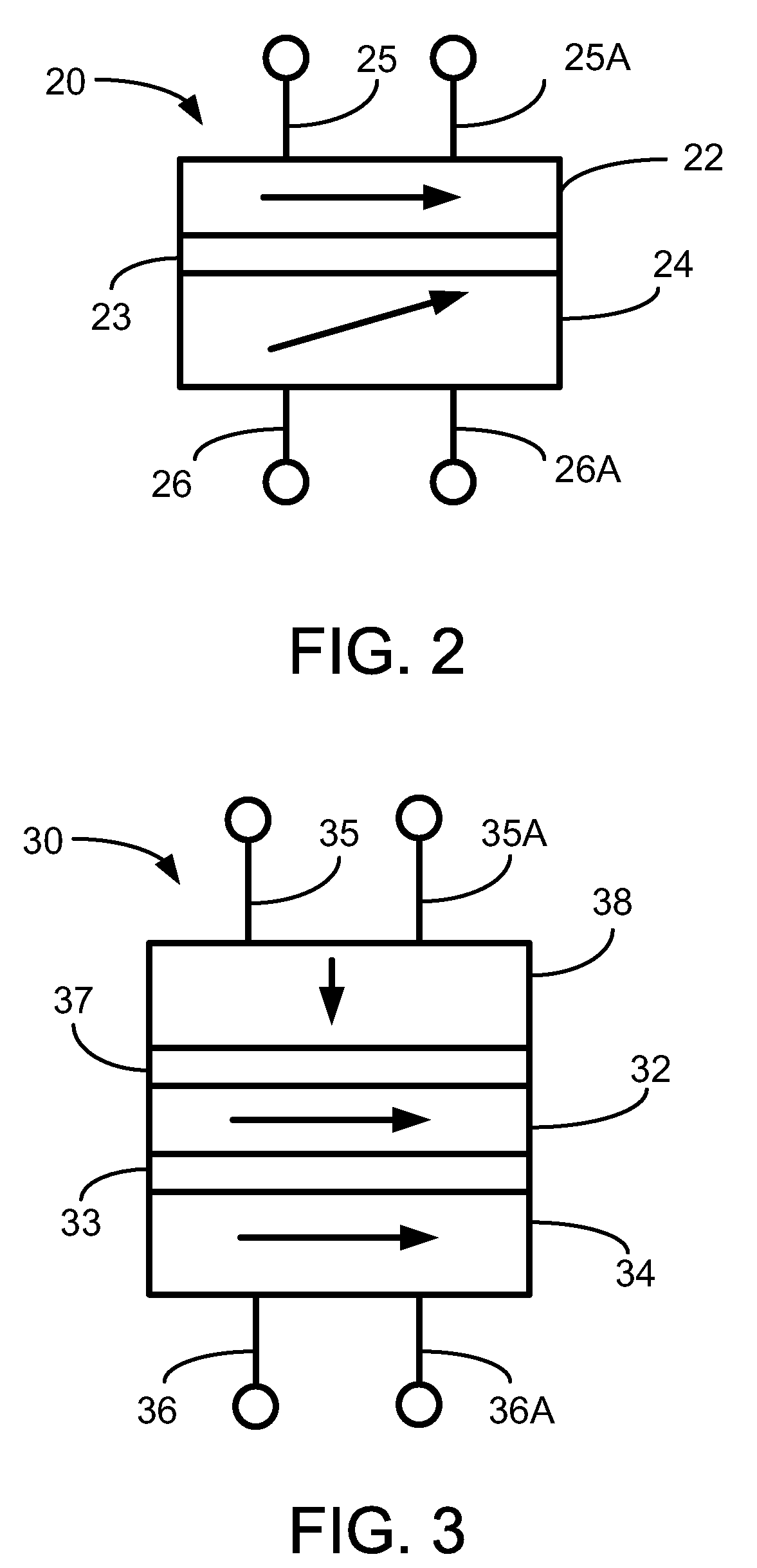
[0006]The present disclosure relates to a spin torque-based magnetic memory that uses a time dependent AC current in conjunction with a DC current to reduce the switching current needed and to improve the switching performance of the memory cell. The memory includes a spin torque memory cell having a switchable magnetic layer that functions as a memory element and another magnetic layer that polarizes the AC current at least partially in the direction perpendicular to the memory element's magnetization.

Problems solved by technology

However, their small size also creates issues.
One problem is an excessive heat generation caused by the use of currents with high amplitude to switch the magnetization orientation of the memory cells.
Among other things, this temperature increase reduces the stability of the magnetic elements.
Another problem is a relatively long typical switching time (e.g., many nanoseconds) of such elements.

Method used


Image

  • Oscillating current assisted spin torque magnetic memory
  • Oscillating current assisted spin torque magnetic memory
  • Oscillating current assisted spin torque magnetic memory

Examples


first embodiment

[0046]A first embodiment is to generate AC current with a constant frequency and generate a series of bipolar current pulses which follow the changes in the frequency of the uniform mode. In one particular example, an AC current of 0.15 mA, polarized perpendicular to the free layer, and a DC current, polarized along the semi-major axis of the free layer, are applied. At optimal frequency (approximately 0.66 of a small angle resonant frequency) the DC current needed to switch the magnetization is reduced significantly due to the presence of the AC current. The width of the frequency window during which the switching current is reduced is proportional to the strength of the AC current.

second embodiment

[0047]A second embodiment is to use “chirped” AC pulses, a particular implementation of which is shown in FIG. 4. The specific numerical values indicated in FIG. 4 were obtained by modeling for a specific set of spin torque memory cell and current value parameters. In FIG. 4, the magnetization MZ / MS is illustrated as a function of time for switching with an optimized sequence of square pulses with an amplitude I0=0.17 mA. The chirped AC pulses constantly resonantly excite the uniform precession of the magnetization, which corresponds to aJ having the opposite sign to the value of MxMz, so that the switching can be performed with small AC current, even in the absence of a DC current. Levels as low as 0.05 mA of AC current reduce the DC current switching threshold to 0.3 mA. Switching speed is also greatly reduced, dependant on the value of applied AC current.

[0048]FIG. 5 illustrates the switching time as a function of chirped AC current amplitude, in the absence of DC current. The nu...


PUM


Abstract

A memory unit having a spin torque memory cell with a ferromagnetic free layer, a ferromagnetic pinned layer and a spacer layer therebetween, with the free layer having a switchable magnetization orientation with a switching threshold. A DC current source is electrically connected to the spin torque memory cell to cause spin transfer torque in the free layer. An AC current source is electrically connected to the spin torque memory cell to produce an oscillatory polarized current capable of spin transfer torque via resonant coupling with the free layer.

Description

RELATED APPLICATIONS[0001]This application claims priority to U.S. provisional patent application No. 61 / 086,864, filed on Aug. 7, 2008. The entire disclosure of application No. 61 / 086,864 is incorporated herein by reference.BACKGROUND[0002]Spin torque transfer technology, also referred to as spin electronics, which is based on changing magnetic state of the system by momentum transfer to conduction electrons, is a recent development. The digital information or data, represented as a “0” or “1”, is storable in the alignment of magnetic moments within a magnetic element. The resistance of the magnetic element depends on the moment's alignment or orientation. The stored state is read from the element by detecting the component's resistive state.[0003]The magnetic element, in general, includes a ferromagnetic pinned layer and a ferromagnetic free layer, each having a magnetization orientation, and a non-magnetic barrier layer therebetween. The magnetization orientations of the free lay...

Claims


Application Information

Patent Timeline
Patent Type & Authority Patents(United States)
IPC IPC(8): G11C11/00
CPCG11C11/16H03B15/006G11C11/161G11C11/1675
Inventor RIVKIN, KIRILLCHEN, YIRANWANG, XIAOBINXI, HAIWEN
Owner SEAGATE TECH LLC
Why Eureka
Try Eureka