
Semiconductor device and method for fabricating the same

A manufacturing method and semiconductor technology, applied in semiconductor/solid-state device manufacturing, semiconductor devices, electric solid-state devices, etc., can solve the problems of deterioration of the characteristics of capacitive elements, inability to realize semiconductor devices with excellent characteristics, and deterioration of characteristics of capacitive elements 111, etc.

Inactive Publication Date: 2004-03-31
PANASONIC CORP
View PDF1 Cites 1 Cited by
  • Summary
  • Abstract
  • Description
  • Claims
  • Application Information

AI Technical Summary

Problems solved by technology

The first problem is that hydrogen generated during the formation of the first interlayer insulating film 118 causes a reduction reaction of the capacitive insulating film 109, that is, the characteristics of the capacitive element 111 deteriorate.
The second problem is that after the formation of the first interlayer insulating film 118, the moisture in the first interlayer insulating film 118 diffuses over time and reaches the capacitive element 111, so that the characteristics of the capacitive element 111 deteriorate.
As a result, the high dielectric or ferroelectric constituting the capacitive insulating film 109 is reduced, so that the characteristics of the capacitive element 111 deteriorate.
In addition, in addition to the above-mentioned OH groups that reach the capacitive element 111 over time, when the heat treatment at 400° C. or higher is performed after the formation of the first interlayer insulating film 118, the OH groups are also likely to reach the capacitive element 111, causing the capacitive element 111 to collapse. Characteristics go bad
[0016] In other words, in existing semiconductor devices, the deterioration of the characteristics of the capacitive element due to the reduction reaction of the capacitive insulating film made of insulating metal oxide cannot be prevented, and a semiconductor device with excellent characteristics cannot be realized.

Method used


Image

  • Semiconductor device and method for fabricating the same
  • Semiconductor device and method for fabricating the same
  • Semiconductor device and method for fabricating the same

Examples


Embodiment Construction

[0102] (first embodiment)

[0103] Next, the semiconductor device and its manufacturing method according to the first embodiment of the present invention will be described with reference to the drawings.

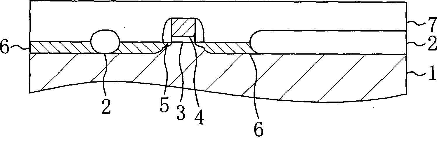
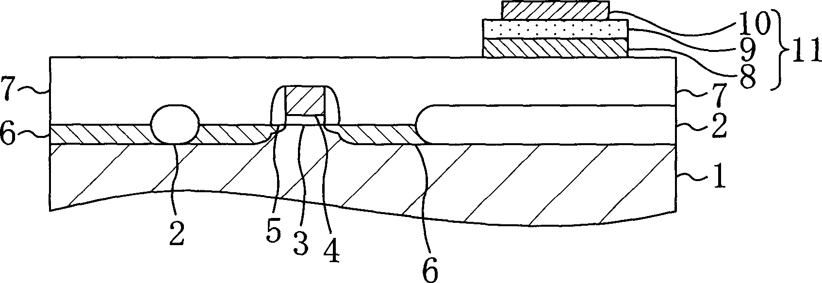
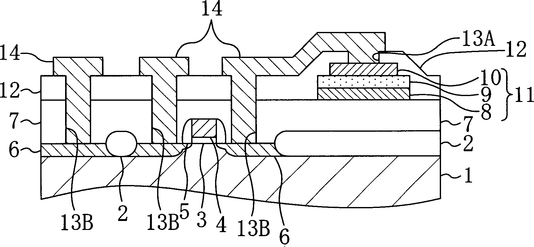
[0104] Figure 1(a) and Figure 1(b), Figure 2(a), Figure 2(b) and image 3 It is a sectional view showing each step of the manufacturing method of the semiconductor device according to the first embodiment of the present invention.

[0105] First, as shown in FIG. 1( a ), an element formation region is separated by providing an element isolation insulating film 2 on a semiconductor substrate 1 , and then a gate 4 is formed on the element formation region via a gate insulating film 3 . Next, insulating sidewalls 5 are formed on both sides of the gate 4, and impurity diffusion layers 6 to be source regions or drain regions are formed on the semiconductor substrate 1 in the device formation region. Next, a first protective insulating film 7 is formed over the entire semiconduc...


PUM


Abstract

A semiconductor apparatus is provided by the present invention. It can prevent the reduction of the capacitor insulating film that contains insulated metallic oxide under the condition that the high temperature oxygen annealing cannot be applied after the interconnection layer being formed. Form capacitor 11 on a semiconductor substrate 1. The capacitor is composed of bottom electrode 8, capacitor insulated film 9 that contains metallic oxide and top electrode 10. A first interconnection layer 14 is formed on the insulated protection film 12 that covers the capacitor 11. A first insulated interlayer film 15 is formed on the first interconnection layer 14 and overlapped the said capacitor 11. A second insulated interlayer film 17 is formed by using the hydrogen block film 16. A second interconnection layer 19 is formed on the second insulated interlayer film 17. The hydrogen-containing rate of the first insulated interlayer film 15 is below the rate of the second insulated interlayer film 17.

Description

technical field [0001] The present invention relates to a semiconductor device having a memory element composed of a lower electrode, a capacitive insulating film made of insulating metal oxide, and an upper electrode. technical background [0002] In recent years, with the development of digital technology, the tendency to process or store large-capacity data has deepened, and electronic equipment has also been further advanced. As a result, the miniaturization of semiconductor devices used in electronic equipment or semiconductor elements mounted on the semiconductor devices is rapidly advancing. Subsequently, in order to achieve high integration of dynamic RAM (Random Access Memory), it is necessary to replace the existing silicon oxide or silicon nitride with a dielectric with a high dielectric constant (hereinafter referred to as a high dielectric) Research and development related to the technology of capacitive insulating films used as capacitive elements is being car...

Claims


Application Information

Patent Timeline
Patent Type & Authority Applications(China)
IPC IPC(8): H01L21/02H01L21/768H01L21/8246H01L27/115
CPCH01L27/11507H01L21/76832H01L21/76834H01L27/11502H01L28/55H10B53/30H10B53/00H10B99/00
Inventor 长野能久伊东丰二今西贞之藤井英治
Owner PANASONIC CORP
Learn More