Hero-turbine centrifuge with drainage enhancing baffle devices

A technology of centrifuge and liquid outlet, which is applied to centrifuges and centrifuges with rotating drums, etc., can solve the problems of unusable centrifuges and so on.

Inactive Publication Date: 2004-04-07
FLEETGUARD INC
View PDF3 Cites 1 Cited by
  • Summary
  • Abstract
  • Description
  • Claims
  • Application Information

AI Technical Summary

Problems solved by technology

In this flooded state, the centrifuge becomes unusable as it can no longer spin at the required speed and separate particles from the oil

Method used


Image

  • Hero-turbine centrifuge with drainage enhancing baffle devices
  • Hero-turbine centrifuge with drainage enhancing baffle devices
  • Hero-turbine centrifuge with drainage enhancing baffle devices

Examples


Embodiment Construction

[0015] To facilitate an understanding of the principles of the invention, reference is made to the embodiments illustrated in the drawings and specific terminology is used to describe the same structures. It should be understood, however, that the scope of the invention is not thereby limited in any way, and those skilled in the art to which the invention pertains contemplate similar alterations and further modifications to the devices described and in accordance with the principles of the invention as described. Further applications are usually possible.

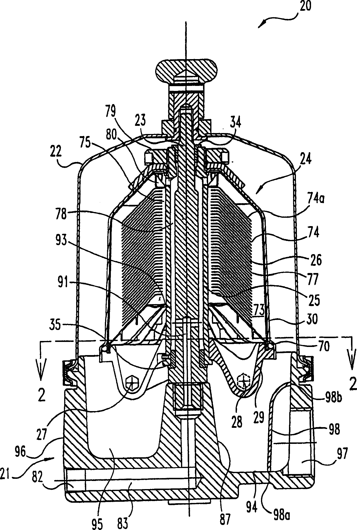
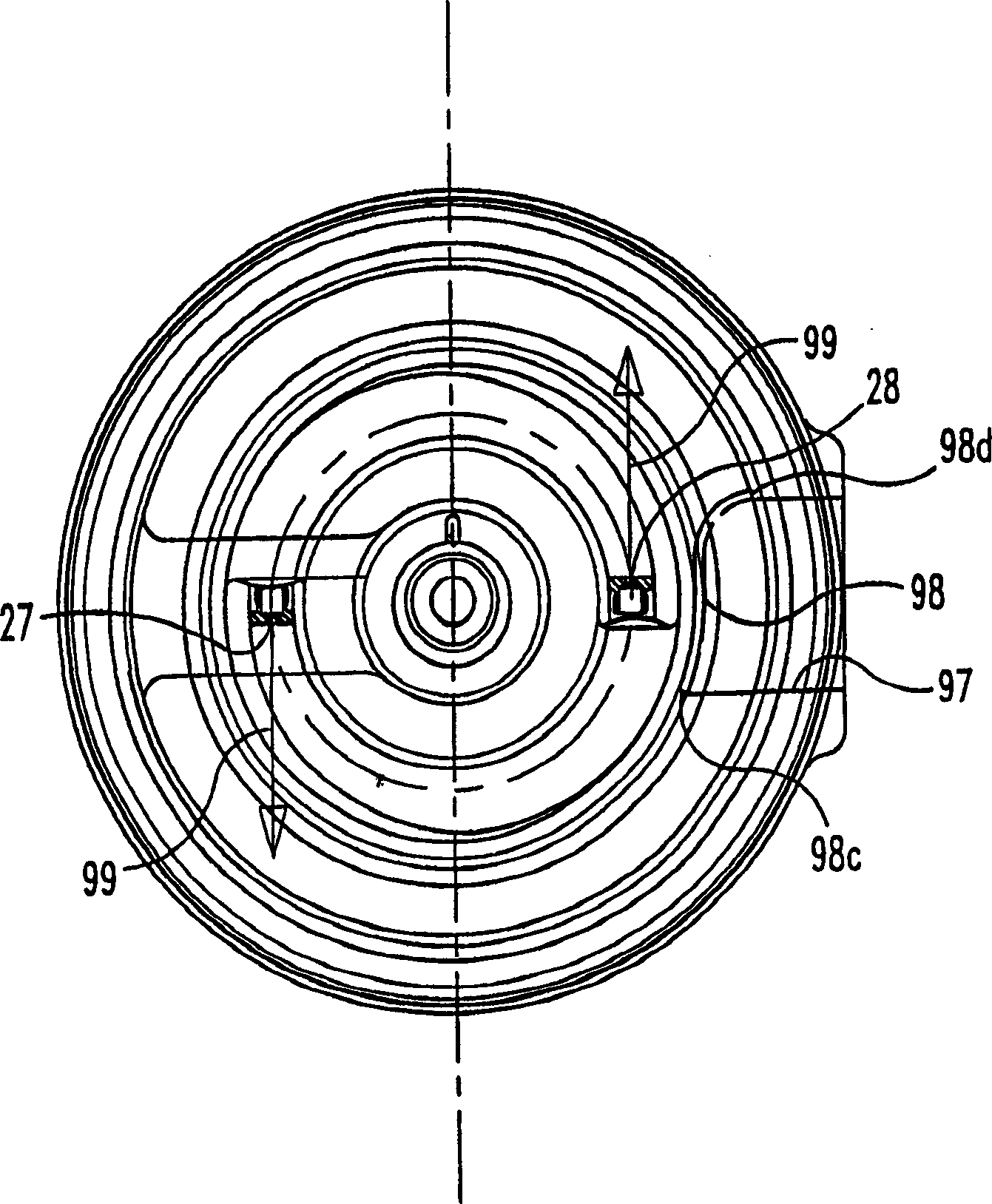
[0016] see figure 1 , which shows a stacked cone centrifuge 20 according to a preferred embodiment of the present invention. The centrifuge 20 includes, as its main components, a base 21, a bell 22, a shaft 23 and a rotor assembly 24 including a rotor hub 25, a stack of cones 26, tangential flow nozzles 27 and 28 , a bottom plate 29 and a centrifuge bowl 30 closed on the bottom plate 29 in a fixed manner. A hollow rotor ...


PUM


Abstract

A cone-stack centrifuge (20) for separating particulate material out of a circulating fluid includes a rotor assembly (24) configured with a hollow rotor hub (25) and is constructed to rotate about an axis by the ejection of the fluid from nozzles (27) in the rotor assembly (24). The rotor assembly (24) is mounted on a shaft (23) that is attached to the hub (87) of a base (21). The base (21) further includes a fluid inlet (82), a passageway (83) connected to the inlet (82) and in fluid communication with the rotor assembly (24), and fluid outlet (97). A bearing arrangement (34, 35) is positioned between the rotor hub (25) and the shaft (23) for rotary motion of the rotor aseembly (24) about the shaft (23). The base (21) further inlcudes a baffle (98) for redirecting a swirling flow of fluid out of the base (21) in a radial direction and into the fluid outlet (97).

Description

Technical field: [0001] The present invention generally relates to the continuous separation of solid particles, such as carbon black, from a liquid, such as oil, by means of a centrifugal force field. In particular, it relates to the construction of stacked cone (disk) centrifuges employing a centrifuge assembly having a base that redirects the residual velocity of the fluid discharged from the rotor nozzle to increase the discharge rate and reduce oil accumulation in the centrifuge base . Background technique: [0002] In an effort to keep dirt and debris out of the engine, diesel engines are designed with the best possible air and fuel filters (filters). Even with these air and fuel filters, dirt and debris, including wear debris from the engine, can still get into the engine oil. The result is wear and tear on delicate engine components. If this condition is not resolved or corrected, the engine will malfunction. For this reason, many engines are designed with full-f...

Claims


Application Information

Patent Timeline
Patent Type & Authority Applications(China)
IPC IPC(8): B04B1/08B04B5/00
CPCB04B5/005B04B1/08
Inventor P・K・赫尔曼K・索斯
Owner FLEETGUARD INC
Why Eureka
Try Eureka