
Electroacoustic transducer

An electro-acoustic sensor, sensor technology, applied in the direction of sensor, inductor/transformer/magnet manufacturing, transformer/inductor coil/winding/connection, etc., can solve problems such as distortion, and achieve the effect of reducing stray magnetic fields

Inactive Publication Date: 2004-04-14
GETTOP EURO R&D
View PDF0 Cites 4 Cited by
  • Summary
  • Abstract
  • Description
  • Claims
  • Application Information

AI Technical Summary

Problems solved by technology

Coils that are not perfectly centered will cause the same distortion as above

Method used


Image

  • Electroacoustic transducer
  • Electroacoustic transducer
  • Electroacoustic transducer

Examples


Embodiment Construction

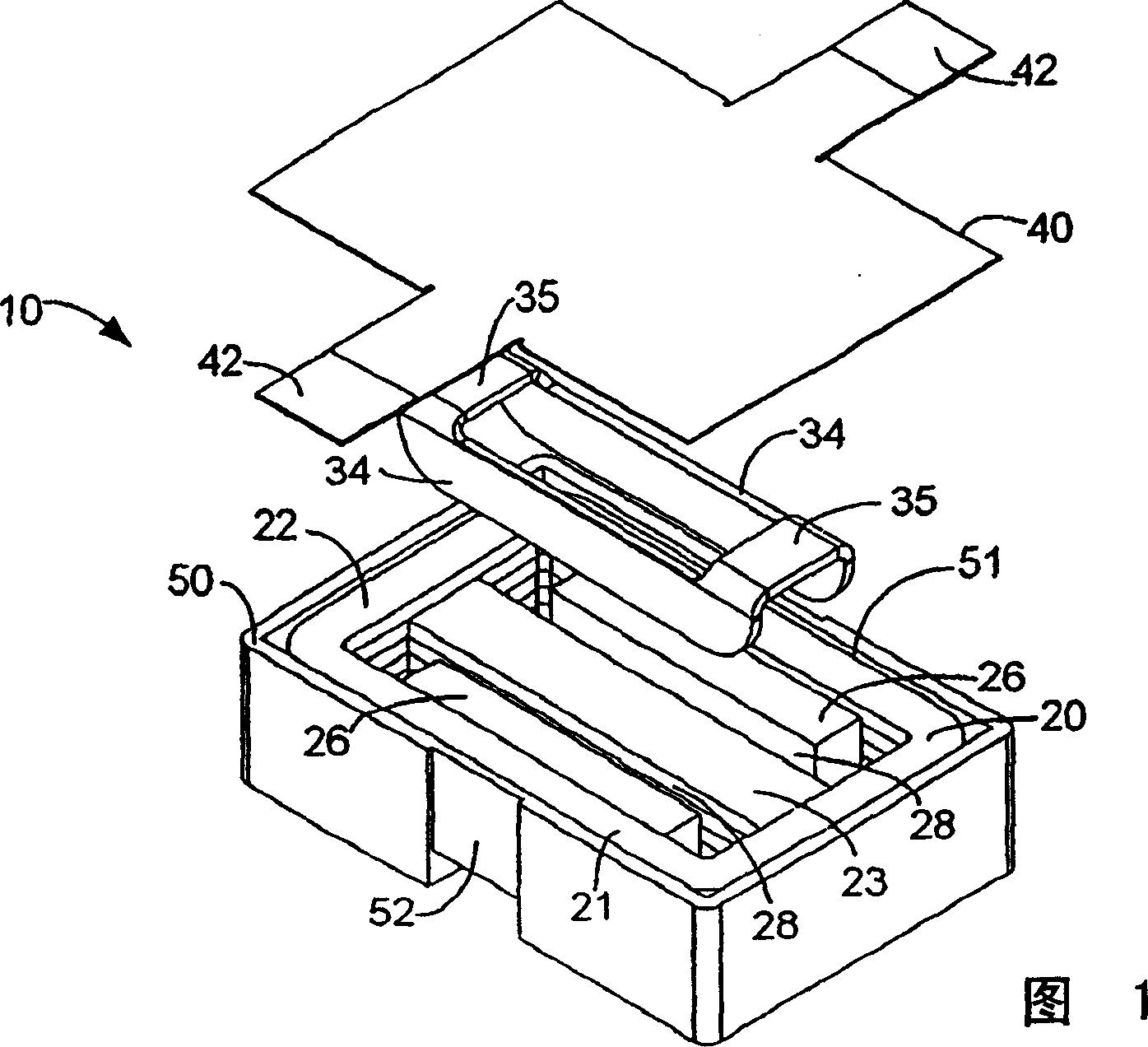
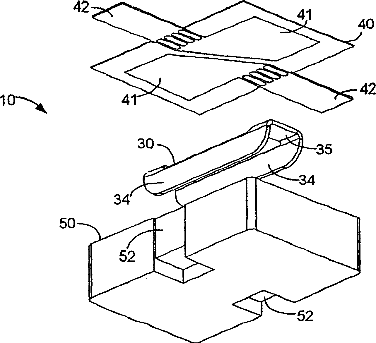
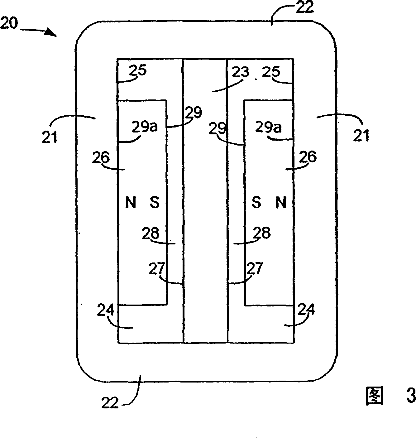
[0011] 1 and 2 show an electrodynamic sensor 10 whose main components include: a magnetic circuit 20 , a coil 30 and a diaphragm 40 . FIG. 3 also shows the magnetic circuit 20 .

[0012] As best seen in Figure 3, the magnetic circuit 20 has two long arms 21 and two short arms 22, the terminals of which are connected together to form a generally rectangular ring. An intermediate arm 23 is connected between the two short arms 22 and divides the interior of the rectangular ring into two rectangular openings 24 . The two long arms 21, the two short arms 22 and the middle arm 23 of the magnetic circuit are soft magnetic materials preferably with high magnetic saturation values. The surfaces of the two long arms 21 and the intermediate arm 23 facing the opening 24 are generally planar and define a gap therebetween. On the planar side 25 of each long arm 21 facing the opening 24 there is a magnet 26 attached to the side 25 . Each magnet 26 has a pole surface attached to the long a...


PUM


Abstract

An electroacoustic transducer comprising a magnetic circuit of a magnetically conductive material with a pair of opposed surfaces defining a gap therebetween, the magnetic circuit comprising a magnet inducing a magnetic field in the gap, the magnet having a surface constituting one of the opposed surfaces. The magnetic circuit further comprises a diaphragm and a coil having electrically conducting paths secured to the diaphragm. The coil has portions of its paths situated in the gap.

Description

field of invention [0001] The present invention relates to electroacoustic sensors, and more particularly to electrokinetic sensors with a diaphragm with a coil movable in a magnetic field. Background technique [0002] Electroacoustic sensors, especially electrodynamic sensors, are widely used in communication equipment requiring small size, such as wired or mobile phones. Conventional electrodynamic microphone and speaker transducers used eg in mobile phones are rotationally symmetrical and have a disc or ring-shaped permanent magnet which is magnetized in the axial direction of the magnet. A magnetic circuit of magnetized soft iron or other suitable material defines a gap with a radial magnetic field established by the magnet. A diaphragm with a toroidal coil of conductive wire positioned in the gap. [0003] If the inner and outer components defining the gap are not perfectly coaxial, the gap will not have a uniform width, which results in distortion of the magnetic fi...

Claims


Application Information

Patent Timeline
Patent Type & Authority Applications(China)
IPC IPC(8): H01F7/06H01F27/30H01F41/071H01F41/10H04R7/04H04R7/12H04R9/02H04R9/04H04R9/06H04R9/08
CPCH04R9/025H04R9/08H01F27/306H04R9/047H01F7/066H01F2041/0662H01F41/10H04R9/046H04R7/12H04R2499/11H04R9/06H01F2041/0711
Inventor K·B·汉森L·约翰森
Owner GETTOP EURO R&D
Learn More