
Permanent magnet array for a rotor of a magnetic bearing and method of assembling the array

A magnet array and magnetic bearing technology, applied in the field of magnetic bearings, can solve problems such as limited effects and expensive shielding

Active Publication Date: 2018-05-25
EDWARDS LTD
View PDF5 Cites 0 Cited by
  • Summary
  • Abstract
  • Description
  • Claims
  • Application Information

AI Technical Summary

Problems solved by technology

[0013] Although ferromagnetic shielding is commonly used to reduce such magnetic field emissions, such shielding is expensive and has only limited effectiveness

Method used


Image

  • Permanent magnet array for a rotor of a magnetic bearing and method of assembling the array
  • Permanent magnet array for a rotor of a magnetic bearing and method of assembling the array
  • Permanent magnet array for a rotor of a magnetic bearing and method of assembling the array

Examples


Embodiment Construction

[0032] image 3 is a schematic diagram of an apparatus for performing measurements according to the invention. Magnet measurement station (or magnetic alignment equipment) 50 includes magnet rotation sections 58 , 60 , 62 , 64 , 66 and magnetic field measurement sections 56 , 54 , 68 , 70 , 72 .

[0033] The magnet rotation section includes a motor 62 for rotating the magnets. Motor 62 is driven by a speed control device 64 (eg, an inverter) and a power source 66 . A non-magnetic spindle or rotor 60 attached to a motor 62 extends up through the non-magnetic table 52 into a magnet mount 58 (also non-magnetic). The motor is positioned sufficiently far from both the magnet mount and the measurement station so that any magnetic field emanating from said motor 62 does not interfere with any measurements taken. The rotor is preferably supported by non-magnetic bearing means (not shown) at the end remote from the motor, proximate the magnet mount 58, to ensure that the magnets can...


PUM


Abstract

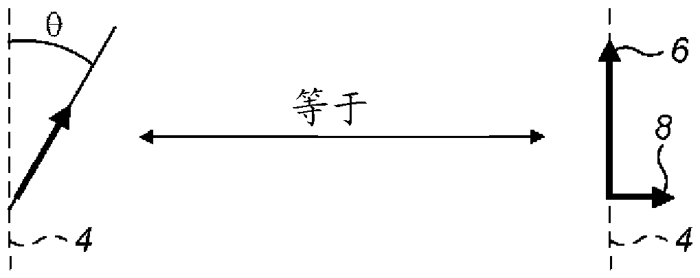
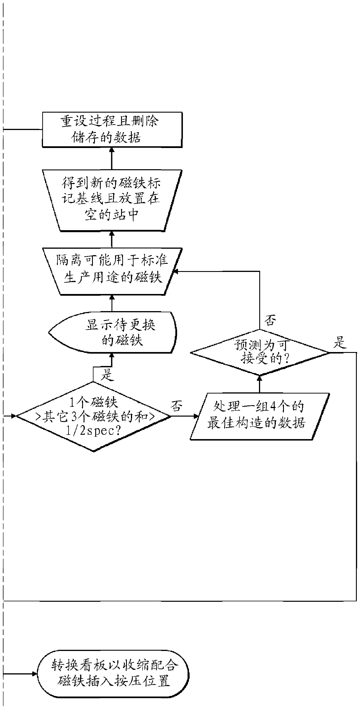
Stray magnetic fields produced by the asymmetric magnetization of the permanent magnets in the rotating magnet array of the magnetic bearing assembly can cause significant problems for devices such as scanning electron microscopes when used in turbomolecular pumps. To minimize stray fields, first measure at least the dipole and quadrupole moments of the individual magnets in the array. The magnets in the array are then arranged relative to each other such that both dipole and quadrupole moments are minimized, thereby minimizing stray magnetic fields as the magnet array in the turbomolecular pump rotates.

Description

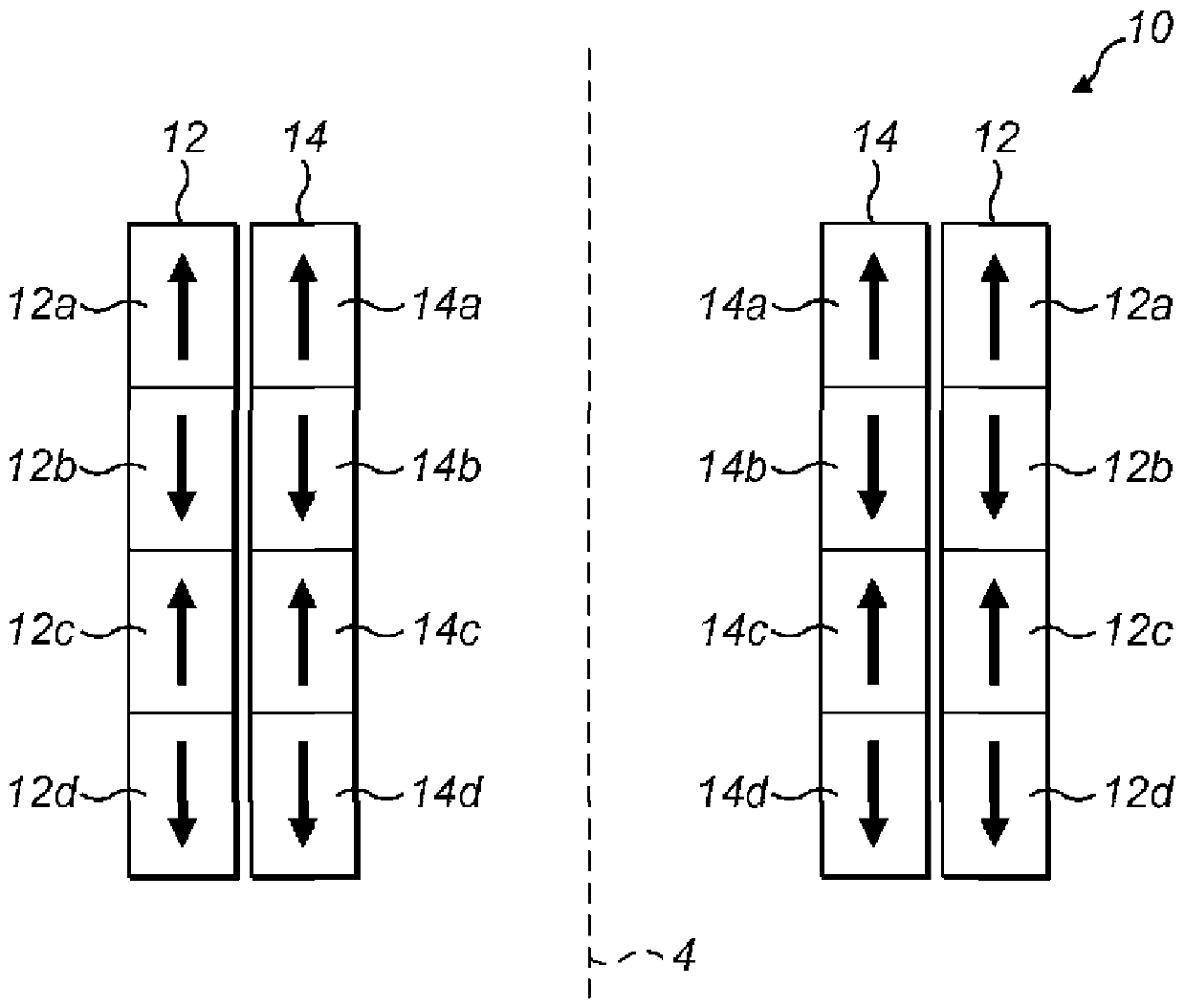
technical field [0001] The invention relates to the field of magnetic bearings. In particular, it relates to an apparatus and method for reducing transverse stray magnetic fields caused by permanent magnetic bearing arrangements in high speed rotating machines such as turbomolecular pumps. Background technique [0002] Turbomolecular pumps are used as part of vacuum systems used to generate the high vacuum environments required for devices such as scanning electron microscopes (SEM) and lithography devices. [0003] Turbomolecular pumps commonly include an oil-free passive permanent magnetic bearing arrangement in the high vacuum end of the pump. [0004] figure 1 A section of a passive permanent magnetic bearing arrangement 10 of a turbomolecular pump (not shown) is shown in . In this example, the bearing arrangement 10 includes an array 12 of four outer rotating permanent magnet rings 12a, 12b, 12c and 12d and an array 14 of four inner non-rotating permanent magnet ring...

Claims


Application Information

Patent Timeline
Patent Type & Authority Patents(China)
IPC IPC(8): F16C32/04G01R33/12H01F7/02H01F41/02
CPCF16C32/0425G01R33/1215H01F7/0236F16C2360/45Y10T29/49004F16C43/00F04D19/048F16C32/0406F16C39/063G01P3/487F16C32/04
Inventor B.D.布鲁斯特A.韦
Owner EDWARDS LTD
Learn More