
Pneumatic self sucking high-pressure oil ejector

A high-pressure oil injection, self-priming technology, applied in the direction of engine components, engine lubrication, mechanical equipment, etc., can solve the problems affecting the pressure value of the oil injection port, the pressure of the oil injection port is unstable, and the maintenance amount is large. Simple, energy-saving effect

Inactive Publication Date: 2004-04-21
程虎
View PDF0 Cites 4 Cited by
  • Summary
  • Abstract
  • Description
  • Claims
  • Application Information

AI Technical Summary

Problems solved by technology

[0003] The oil injection pump products of the same kind abroad adopt the pull-type oil injection method. Its structure is that the oil storage device and the main engine are integrated, and it has a complete set of components such as connecting pipes, nylon pistons, four-legged valves, lifting rods, and lifting plates. The structure is complex. A large amount of maintenance; the principle is: rely on the working frequency of the lifting device to ensure the pressure of the oil injection port, and a slight fluctuation of the compressed air will directly affect the pressure value of the oil injection port, making the pressure of the oil injection port unstable

Method used


Image

  • Pneumatic self sucking high-pressure oil ejector
  • Pneumatic self sucking high-pressure oil ejector
  • Pneumatic self sucking high-pressure oil ejector

Examples


Embodiment Construction

[0020] The present invention will be described in detail below in conjunction with the accompanying drawings and embodiments.

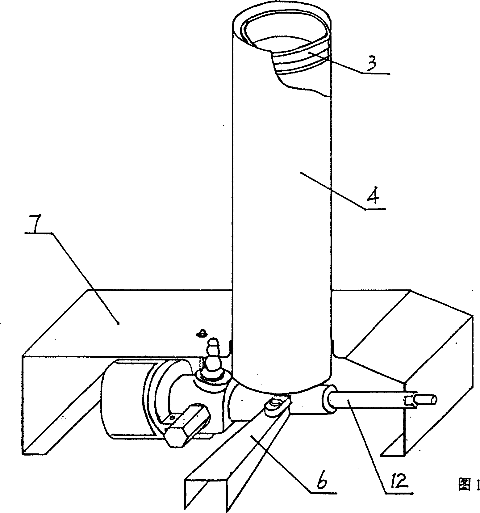
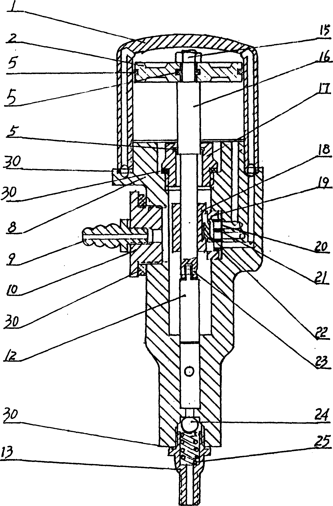
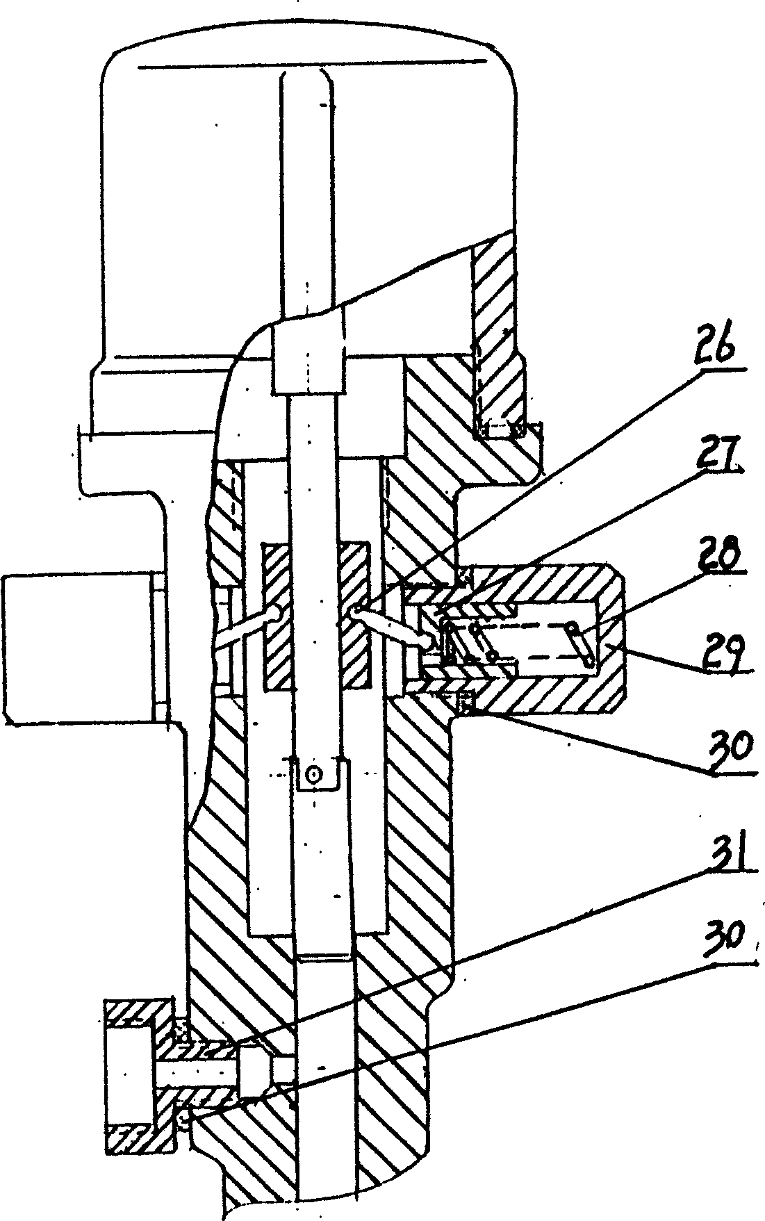
[0021] As shown in Figures 1, 2, and 3, the present invention includes an oil storage mechanism and an oil injection mechanism, wherein the oil storage mechanism is composed of an oil storage cylinder 4 and a large piston 3, the oil injection mechanism is composed of a plunger 12 and a check valve, and the plunger 12 There is a space between one end and the check valve; it also includes an aerodynamic mechanism and an action program control mechanism, which are installed in the box 7; the aerodynamic mechanism is connected to the compressed air source through the compressed air interface 9, and is connected to 16 is connected with the plunger 12 in the oil injection mechanism; the action program control mechanism is installed on the middle part of the valve body 8 and the moving rod 16 in the aerodynamic mechanism; In the power mechanism, the valve bo...


PUM


Abstract

A pneumatic self-sucking type high-pressure oil filler is composed of the oil storage unit consisting of oil storage cylinder and big piston, the oil filling unit consisting of plunger and check valve, the pneumatic unit communicated via interface to the compressed air source and connected via moving rod to plunger, and operation program controller. Its advantages are simple structure, low cost, and high effect to fill a great deal oil in short time.

Description

technical field [0001] The invention relates to an oil injection device, in particular to a pneumatic self-suction high-pressure oil injection device. Background technique [0002] In the prior art, the mutual moving parts of mechanical equipment, especially the high-speed rotating parts, should be lubricated with grease to reduce friction. Usually, the oil guns with this maintenance function are mostly manual, with small oil output, long filling time, and small capacity of the accompanying oil storage tank. It is not suitable for the working environment with multiple use points, large filling volume and short filling time. [0003] The oil injection pump products of the same kind abroad adopt the pull-type oil injection method. Its structure is that the oil storage device and the main engine are integrated, and it has a complete set of components such as connecting pipes, nylon pistons, four-legged valves, lifting rods, and lifting plates. The structure is complex. The ma...

Claims


Application Information

Patent Timeline
IPC IPC(8): F16N11/10
Inventor 程虎李洪伟李来祥
Owner 程虎
Learn More