
Improved burette safety valve

A measuring tube and pipeline technology, applied in the direction of valves, diaphragm valves, valve devices, etc., can solve problems such as difficulty in use and poor versatility

Inactive Publication Date: 2004-04-21
CAREFUSION 303 INC
View PDF1 Cites 8 Cited by
  • Summary
  • Abstract
  • Description
  • Claims
  • Application Information

AI Technical Summary

Problems solved by technology

This arrangement makes it difficult to use and less versatile

Method used


Image

  • Improved burette safety valve
  • Improved burette safety valve
  • Improved burette safety valve

Examples


Embodiment Construction

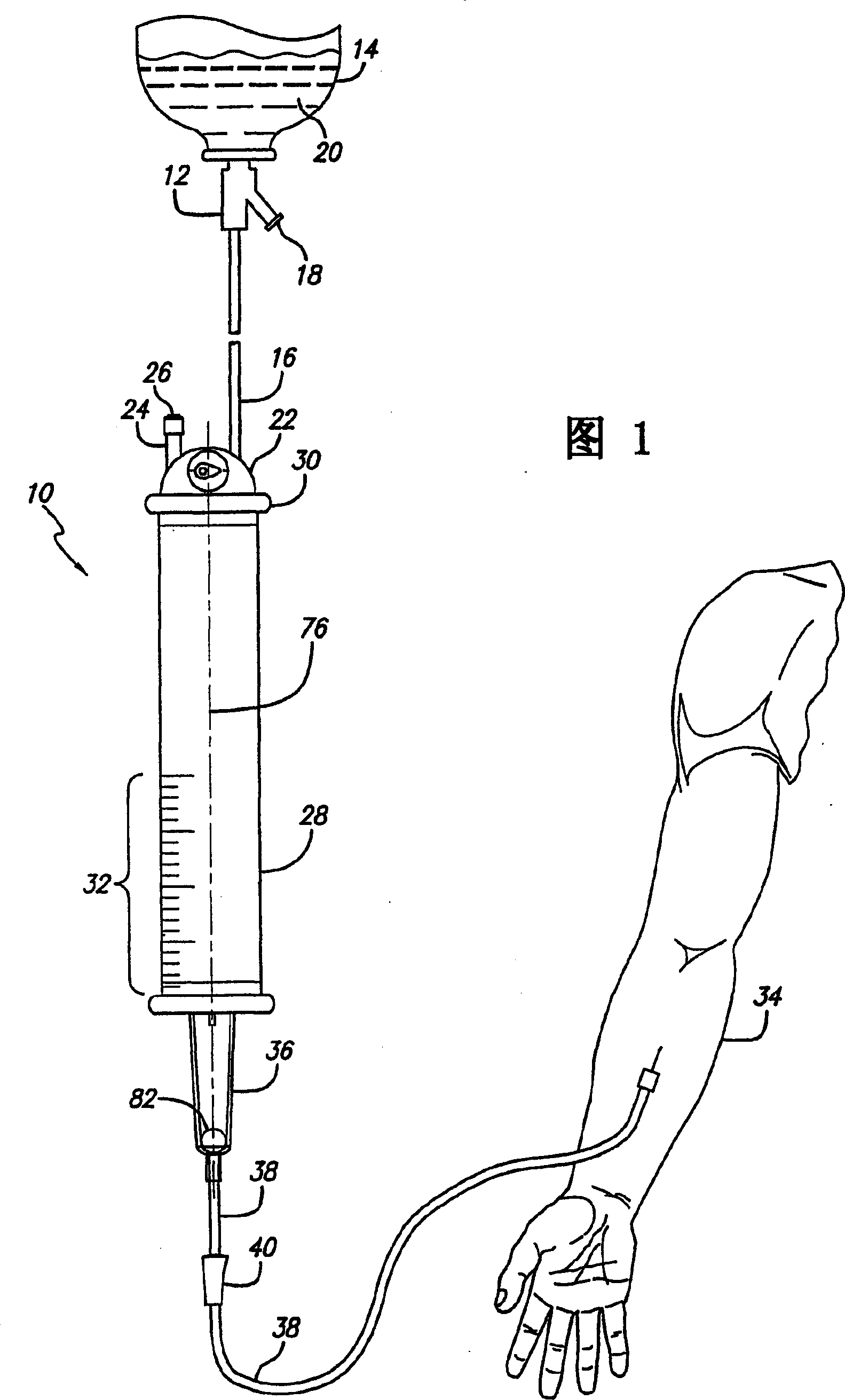
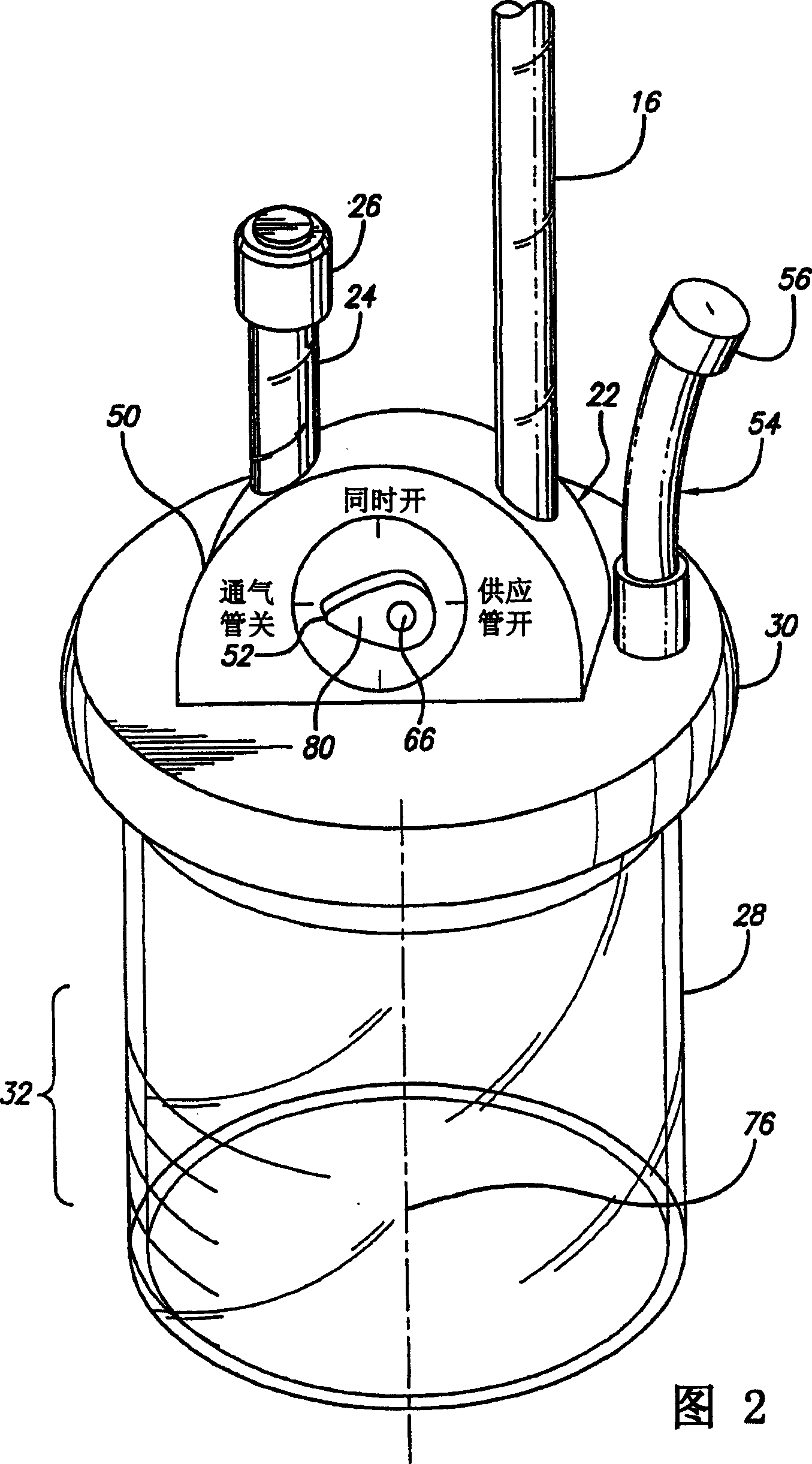
[0033] In the following description, the same reference numerals in different drawings denote the same components. Referring now to FIG. 1, an open drug delivery kit 10 is used to introduce a drug solution into a patient. Those skilled in the art are aware that the spike-shaped tubing 12 used to connect the supply container 14 to the supply tube 16 includes a vent tube 18 so that the liquid medicine 20 can flow continuously from the supply container 14 through the supply tube 16 and into the Fluid flow control system 22 . A flexible bag or other type of receptacle may be used in place of the supply container 14 to more conveniently store the fluid. A vent tube 24 is also connected to the fluid flow control system 22 . A filter 26 is connected to the end of the vent pipe 24 to filter dirt. Fluid flow control system 22 is mounted on burette chamber 28 which controls communication between regulator chamber 28 and supply tube 16 and vent tube 24 through an opening in the top of...


PUM


Abstract

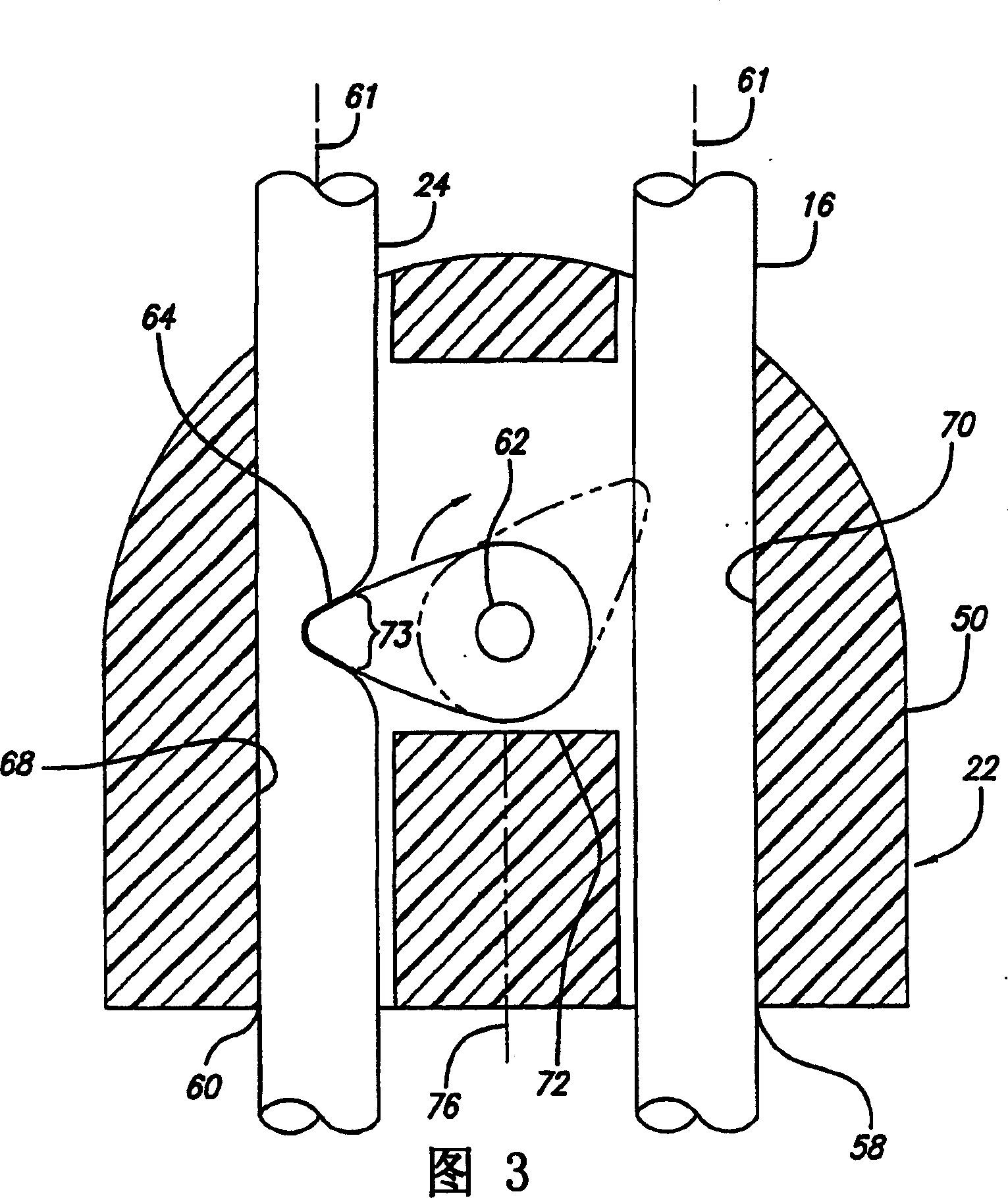
A system for controlling fluid flow through multiple conduits for use in a fluid administration device. The system includes a housing, a cam, and a control element used to move the cam to selectively occlude the conduits. When used with a medical burette, the cam is located between the vent and supply conduits and rotates to alternately occlude one or the other conduits or to leave both conduits patent. A cam lobe occludes the conduits by pressing the conduit against a pressure surface until occlusion is obtained. Depending on the rotational position of the cam, the continuous flow mode, the intermittent flow mode, and the priming mode are all obtained with a single control lever. The housing secures the conduits in predetermined, fixed positions both above and below the contact location of the cam to the conduit. A positive locking device is included to assist in locating the cam in the desired position. A tactile sensation is also provided to the operator by the locking device to indicate that the cam has been placed in the desired location. Clear visual indicators are included on the housing so that the flow mode in which the burette is presently operating can be seen from a distance.

Description

technical field [0001] The present invention relates to an improved valve system for controlling the flow of fluid through a plurality of conduits, and more particularly, the invention relates to a safety valve for controlling the delivery of medical fluids to a patient. Background technique [0002] Medical procedures often require the introduction of fluids into a patient by means of a system such as a parenteral administration set. Some of these kits include multiple independently operable clamps or valves to control the flow of fluid through the administration kit and into the patient. Such kits typically include a vent tube and at least one fluid supply tube connected to a fluid supply container, such as a fluid-filled bag. In order to dispense the fluid, medical personnel or other users manually operate the clamp in the fluid control to open or close the pipeline of the drug delivery kit as needed. These dosing kits may also include injection ports so that medicament...

Claims


Application Information

Patent Timeline
IPC IPC(8): A61M5/168A61M5/14A61M39/00A61M39/28
CPCA61M5/1412A61M39/285A61M5/14
Inventor R·巴特费尔德E·B·安德森
Owner CAREFUSION 303 INC
Learn More