Ultrasonic radiation equipment

A technology of ultrasonic radiation and equipment, applied in ultrasonic therapy, treatment, medical science, etc., can solve problems such as the degradation of ultrasonic image quality

Inactive Publication Date: 2004-05-12
KK TOSHIBA
View PDF4 Cites 11 Cited by
  • Summary
  • Abstract
  • Description
  • Claims
  • Application Information

AI Technical Summary

Problems solved by technology

Most of the ultrasonic waves emitted by the ultrasonic imaging probe 5 are reflected to the surface of the ribs, resulting in a decrease in the quality of the ultrasonic image

Method used


Image

  • Ultrasonic radiation equipment
  • Ultrasonic radiation equipment
  • Ultrasonic radiation equipment

Examples


Embodiment Construction

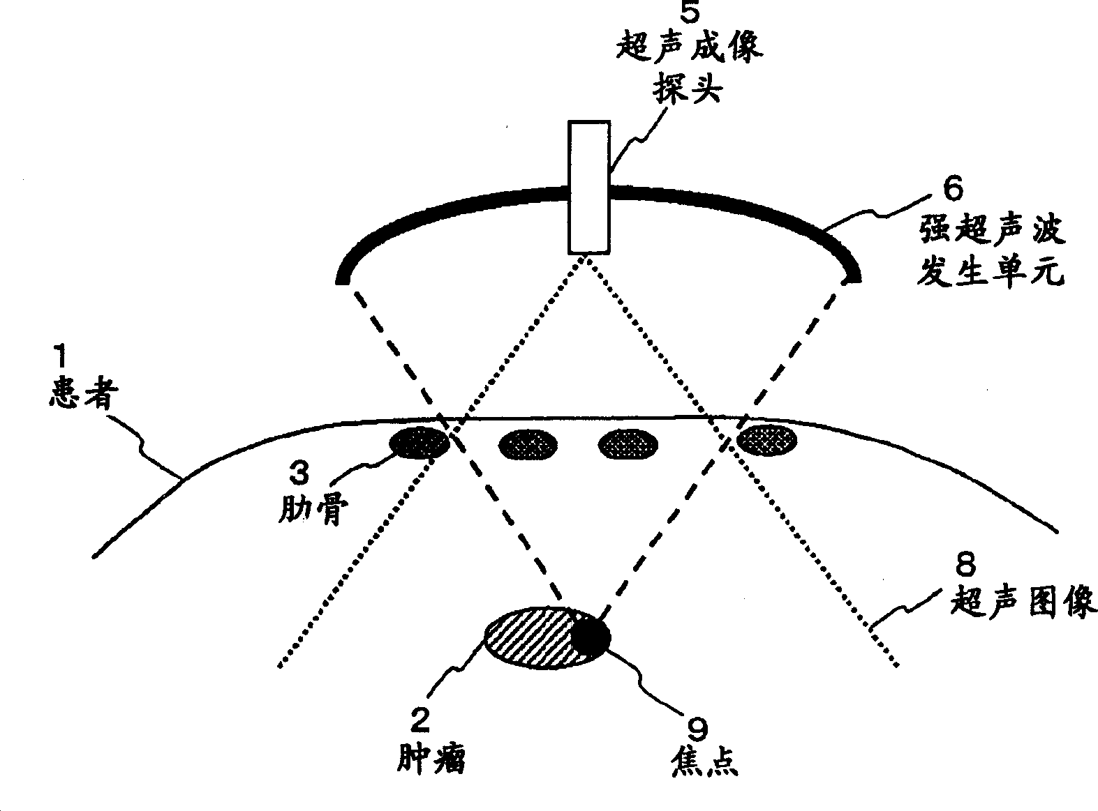
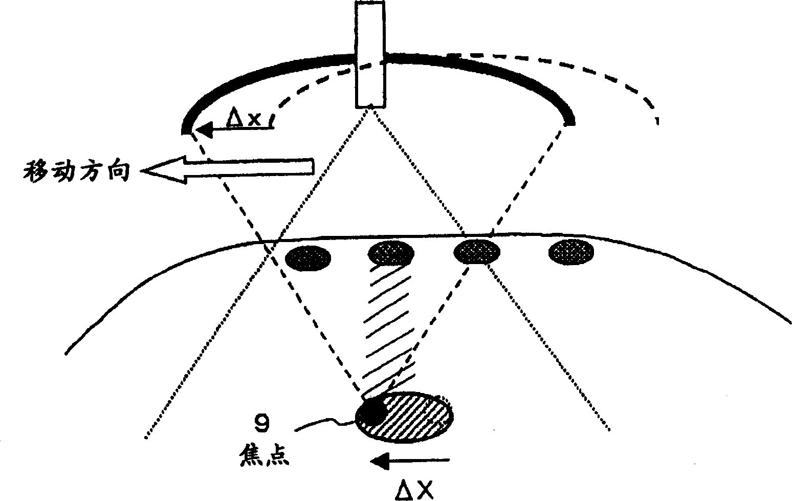
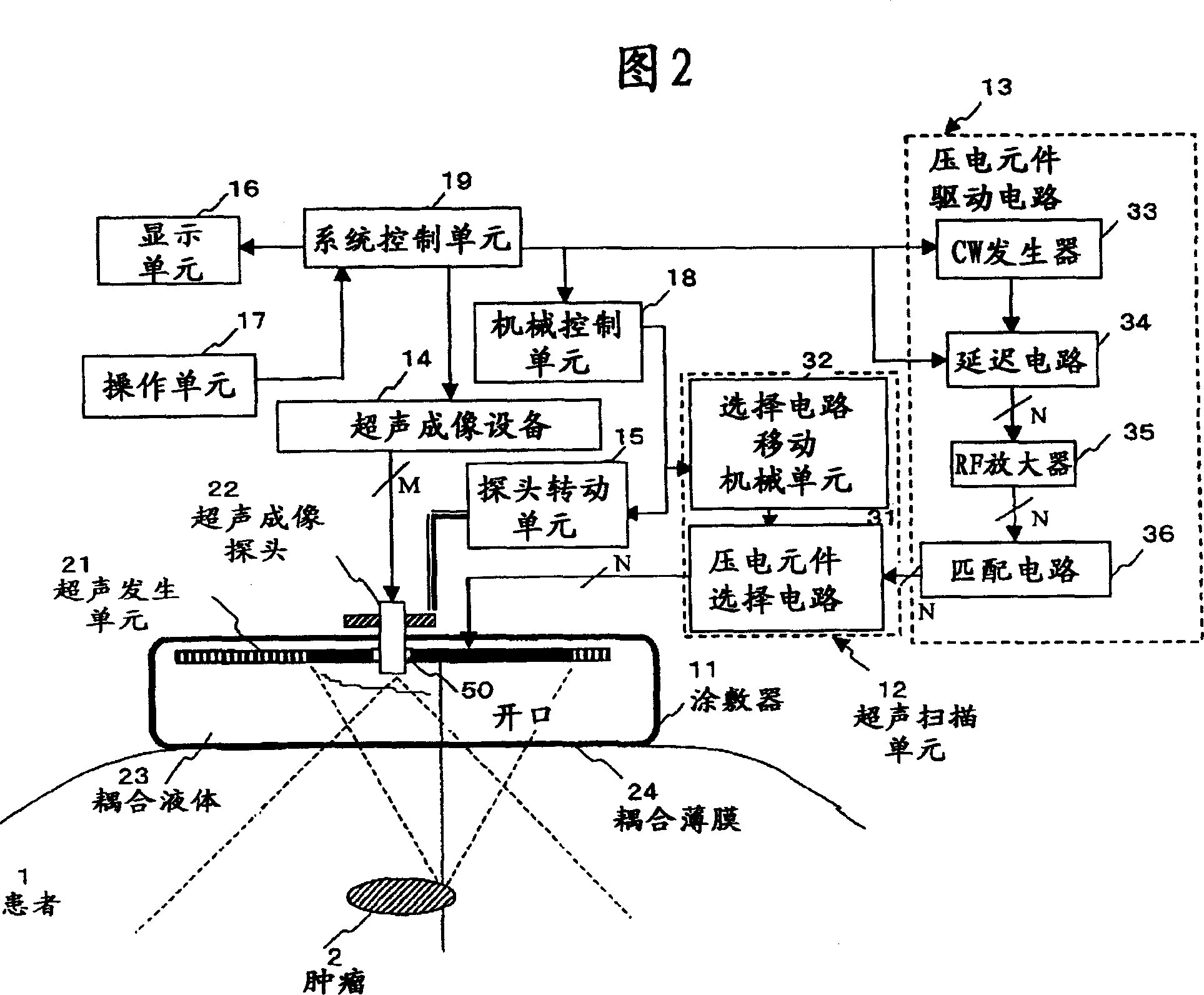
[0043]Referring now to the drawings, in which like reference numerals designate like or corresponding parts throughout the several views, embodiments of an ultrasonic radiation apparatus according to the present invention are explained below with reference to FIGS. 2 to 11 . The ultrasonic radiation apparatus in these embodiments is used for therapy using strong ultrasonic waves to heat tumors or for implementing ultrasonic radiation mixing methods to increase gene transfer efficiency. The ultrasonic radiation device has a plurality of piezoelectric elements arranged two-dimensionally in an applicator that is in contact with a patient. Some piezoelectric elements are selected from the plurality of piezoelectric elements described above by a piezoelectric element selection circuit separate from the applicator.

[0044] The ultrasonic irradiating apparatus will be explained with reference to FIGS. 2, 3A and 3B, which respectively show a block diagram of the ultrasonic irradiatin...


PUM


Abstract

An ultrasound irradiation apparatus which irradiates an ultrasonic wave to a desired area by selecting two or more piezoelectric elements and by changing the selected piezoelectric elements. The selection may be performed by mechanical movement of substrates or electrical switches. A size of an aperture defined by selected irradiating piezoelectric elements may be determined based on a focal distance of an ultrasonic wave focusing is performed by varying delay times of drive signals applied to the selected piezoelectric elements.

Description

[0001] Cross-Referenced Related Applications [0002] This application claims prior Japanese Patent Applications No. 2002-280590 filed September 26, 2002, No. 2002-313673 filed October 29, 2002, and No. 2002-263062 filed September 9, 2002 The entire contents of these earlier applications are hereby incorporated by reference as a basis of priority. technical field [0003] The invention relates to an ultrasonic radiation device for radiating ultrasonic waves to objects. Background technique [0004] In recent years, minimally invasive medical treatments have attracted attention and have been attempted for the treatment of cancer. Since cancer is often treated with surgical procedures, such as surgical removal of tumor-containing tissue, it can result in a reduction in the original function of internal organs, or a defect in appearance. In such a case, even if the life of the patient is maintained, i...

Claims


Application Information

Patent Timeline
Patent Type & Authority Applications(China)
IPC IPC(8): A61B19/00A61N7/00A61N7/02
CPCA61N7/02A61B2019/5276A61N2007/0078A61B2090/378
Inventor 石桥义治藤本克彦
Owner KK TOSHIBA
Why Eureka
Try Eureka